Smart Current Sensors for Isolated High Current (100 A to 1000 A) Applications
High power UPS systems, onboard chargers, traction inverters, fuel cells, battery systems, and other applications require accurate current measurements at high common-mode voltages. Traditionally, these systems used shunt-based current measurement solutions at <50 A and Hall-based solutions when >50 A.
Isolated Current Measurement Methodologies
Texas Instruments’ article “Comparing shunt- and hall-based isolated current-sensing solutions in HEV/EV” by Krunal Maniar looks at electric vehicle applications using isolated high current measurement technologies. The most common methods used are either shunt-based using isolated amplifiers or isolated modulators or Hall-based using open-loop or closed-loop Hall sensors as shown in Figure 1.
 Figure 1: Isolated Current Measurement Methods (Image source: Texas Instruments)
Shunt-based systems are generally easier to implement because they are more linear and offer higher current measurement accuracy than Hall-based methods. Table 1 compares the characteristics of both technologies across several categories.
 Table 1: Comparing Shunt-Based and Hall-Based Methods (Source: Texas Instruments)
Higher power applications, increased efficiency requirements and the growing global market for electric vehicles (EVs) and hybrid electric vehicles (HEVs) requiring increased current measurement accuracy is driving interest in higher current isolated shunt measurement solutions.
Riedon SSA Isolated Smart Current Measurement Technology
Riedon’s SSA Smart Current Sensors integrate a high-power low resistance shunt with an isolated precision amplifier. Models are available with current measurement ranges from 100 A to 1000 A. Key features include 1500 VDC/1000 VAC RMS reinforced isolation, ± 0.1% initial accuracy, ± 0.1% linearity over current range, unipolar power supply, differential analog output, and 300 kHz bandwidth. The functional diagram of the sensor is shown in Figure 2.
 Figure 2: Smart Current Sensor Functional Diagram (Image source: Riedon)
Physical construction consists of a power bus bar with an isolated sensor housing encased around the center of the bar as shown in the SSA-250 in Figure 3. A JST JWPF series four pin connector provides the interface to (1) power, (2) ground, (3) +Vin, and (4) –Vin for the encapsulated sensor. The corresponding mating connector is JST type J04R-JWPF-VSLE-S (housing) and SWPR-001T-P025 (contact).
 Figure 3: SSA-250 (Image source: Riedon)
Riedon’s SSA family consists of four current ratings: 100 A, 250 A, 500 A, and 1000 A. (Note: the 1000 A version uses a wider bus bar with four mounting holes.)
Optional Mounting Hardware and Cable Assembly
For ease of mounting, an optional mounting fixture, the SSA-BASE, is available for models SSA-100 thru SSA-500 as shown in Figure 4. It is constructed of UL 94-V0 rated materials and uses 5/16-18 stainless steel hardware.
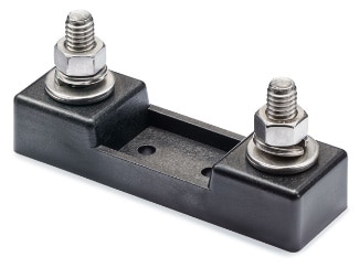 Figure 4: SSA-BASE (Image source: Riedon)
An optional connector cable assembly, the SSA-CABLE-1M, is available and shown in Figure 5. It is compatible with all SSA models and standard cable length is 1 meter.
 Figure 5: SSA-CABLE-1M (Image source: Riedon)
The cable assembly uses the JST mating connector for the SSA-xxx models and two twisted pairs of color coded 22-gauge wire. One twisted pair (red/black) is for the sensor power and ground connections and the other (yellow/white) being the differential (+) and (-) amplifier output signals.
100 Amp Bluetooth Wireless Current Sensor Proof of Concept Project
The scope of the project was to develop a proof of concept 100 A Bluetooth wireless current sensor using Riedon’s SSA-100 sensor and off-the-shelf hardware. For the main controller and Bluetooth connectivity, I used Adafruit’s nRF52840 Feather Express board. I selected this board because it has Bluetooth built-in and supports CircuitPython programming. I have started using CircuitPython in my microcontroller-based projects because it is very capable, easy to use, available on multiple platforms, and has extensive library/example support from Adafruit. Since the SSA-100 sensor’s current signal is represented by a differential analog voltage of 12 mV/A, I added Adafruit’s ADS1115 ADC breakout board. This ADC provides 4 channels, 16-bit accuracy, programmable gain, I2C interface and differential input capability. Figure 6 shows the wiring schematic between the hardware and the Riedon current sensor.
 Figure 6: Bluetooth Current Sensor Scheme-it Schematic (Image source: DigiKey)
The full BOM (Bill of Material) is contained in the below DigiKey Scheme-it® project.
CircuitPython code on the nRF52840 Feather Express sets up the Bluetooth connection and sends current readings from the SSA-100 sensor to an Android phone. Project details, example CircuitPython code and reference links are located in the eeWiki project Bluetooth Wireless 100 Amp Current Sensor.
Test Setup and Results
For testing, I installed the current sensor in series with the 12 V battery in my Honda ATV as shown in Figure 7. Engaging the ATV’s electric winch provided a current load for the current sensor to measure.
 Figure 7: Honda ATV Test Setup (Image source: DigiKey)
Adafruit’s BlueFruit LE Connect mobile app was installed on a Google Pixel phone to display current measurements sent by the nRF52840 Feather Express. The “Plotter” mode in the app was used to display current readings from the SSA-100 when the ATV winch was switched on. Figure 8 shows current readings from the ATV when the winch was engaged in reverse and pull modes.
 Figure 8: BlueFruit LE Connect Plotter Graph (Image source: DigiKey)
Conclusion
Riedon’s SSA current sensors are accurate, versatile and easy to use. They can be used either high-side or low-side side in both AC and DC applications. Since they are highly linear, the sensors can easily be embedded in high power circuits to add accurate isolated current measurement capability.
About this author

Scott Raeker, Principal Application Engineer at DigiKey, has been with the company since 2006. He has over 35 years of experience in the electronics industry and holds an Electrical Engineering degree from the University of Minnesota. In his spare time, Scott enjoys the outdoors of Northwest Minnesota and working on his turn-of-the-century farmhouse.

Have questions or comments? Continue the conversation on TechForum, DigiKey's online community and technical resource.
Visit TechForumRelated Blogs


More Blogs from this Author