How to Connect the Blocks in Commercial Energy Storage Systems
Commercial battery energy storage systems (BESSs) are needed to facilitate the use and grid integration of renewable energy resources like wind power and solar energy. BESSs are complex and include a large battery, battery management system, battery control and communications, and an inverter/transformer. Optimal design of every building block is essential to the overall efficiency and reliability of the BESS, but it’s not enough. Each block must be interconnected to withstand harsh conditions and ensure the best performance. To get that done, designers must mix and match a range of connector types to arrive at the most cost-effective and reliable solutions (Figure 1).
 Figure 1: The blocks that make up a commercial BESS require specific connector solutions for reliable and efficient operation of the overall system. (Image source: Amphenol)
In this blog, I’ll briefly review some of the operational benefits of a BESS, the blocks used to build one, and detail connector options with example connectors from Amphenol.
BESS benefits
Installing a BESS is not necessarily an altruistic affair. In addition to supporting the use and grid integration of renewables, a BESS brings financial benefits including:
Demand charge management: Many facilities are required to pay demand charges based on peak electricity usage. Using a BESS to lower peak energy consumption can reduce overall energy expenditures up to 70 percent1.
Load shifting: Software algorithms can be used to analyze energy consumption patterns compared with time-of-use electricity rates, and determine the best time(s) to discharge the BESS during the highest-cost periods.
Backup power: Power outages can be costly, and a BESS can eliminate the need for a separate uninterruptible power system (UPS), or enable the use of a smaller, less expensive UPS.
BESS blocks
The battery selection requires chemistry to support defined energy storage and power delivery needs, the packaging style for the cells, and the system integration structure such as a battery rack.
The battery management system (BMS) ensures optimal charge and discharge rates, monitors temperature, and estimates the immediate readiness (state of charge) and the anticipated long-term reliability (state of health) of the battery.
Battery control and communication reports on operational status and supports remote control.
The inverter/transformer converts the direct current (DC) battery power to alternating current (AC) power and connects the BESS to the grid.
Key performance factors for connecting these BESS blocks include:
- High power and signal densities
- Ease of installation in the field
- High reliability in rugged and harsh environments
Connecting bus bars
For a high power density battery system solution, designers can turn to the BarKlip BK200 cable assembly to distribute up to 200 amperes (A) per contact between busbars, cables, and circuit boards (Figure 2). It has a maximum resistance of 0.20 milliohms (mΩ) per port, making it highly efficient. This cable assembly enables a direct pluggable connection with a system rack bar and a 3.00 millimeter (mm) thick copper bar, supporting ease of installation. The 14 cantilevered beams provide a compliant spring that adjusts for variations in busbar alignment and surface finish, resulting in high reliability.
 Figure 2: The BarKlip BK200 cable assembly can distribute up to 200 A per contact for battery system interconnects. (Image source: Amphenol)
Connectors for inverters
The PwrBlade+ AC and DC power distribution connector system for applications requiring higher linear current density and low power loss is a good fit for the battery charger and inverter (Figure 3). It supports up to 192 A per linear inch (A/linear in.) with eight adjacent high-power contacts and a contact resistance of ≤0.7 mΩ. These connectors also include low power and signal contacts for a complete solution.
 Figure 3: Battery chargers and inverters can use PwrBlade+ AC and DC power distribution connectors. (Image source: Amphenol)
BMS interconnects
When integrating BMS systems, the CoolPower Slim Drawer Series can be used. It supports up to 60 A per pin and has a 0.4 mΩ end-of-life contact resistance. It’s configurable with various combinations of power and signal contacts, as well as mounting and termination options (Figure 4). Features such as blind-mating, sequential mating, and hot-plug are also important for BMS systems. As application examples, part number DWRT424SV23690 has 28 sockets and part number DWRT820PR233B2 has 28 pins.
 Figure 4: CoolPower Slim Drawer connectors are suited for BMS integration. (Image source: Amphenol)
BMS interconnects in smaller BESSs can benefit from the ComboLock series, a hybrid wire-to-board connector system that saves space, and enables simpler assembly and cable management. These connectors have from five to 19 signal pins and two to eight power pins and come in vertical and right-angle configurations with surface mount terminations (Figure 5). The power pins are capable of carrying up to 10 A. For example, part number 10162688-207206CLF provides eight power pins and seven signal pins, while part number 10162688-205202CLF has two power pins and five signal pins. These connectors have an active latching function for high reliability.
 Figure 5: Smaller BESSs can use ComboLock connectors in the BMS. (Image source: Amphenol)
Connecting with the outside
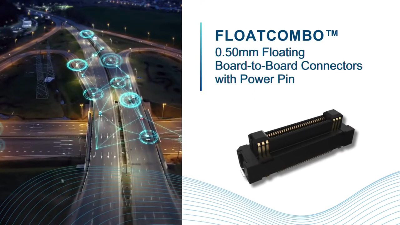
The power pin 0.50 mm pitch floating board-to-board connector system is designed for applications such as the battery control and communications block, which would benefit from a compact solution supporting high-speed communications up to 10 gigabits per second (Gbits/s) and a 5 A power pin (Figure 6). Plug part number B3221B7L111260E100 has 60 positions (bottom) while part number B3291B7L111260E100 (top) has 60 receptacles. For enhanced reliability and ease of assembly, these connectors have an operating temperature range of -55˚C to 125°C, an anti-fool mating design, and direction guide functions for easy mating.
 and the B3291B7L111260E100 (top) board-to-board connectors") Figure 6: Floating board-to-board connectors like the B3221B7L111260E100 (bottom) and the B3291B7L111260E100 (top) support the power and high-speed communications needs of the battery control and communications block. (Image source: Amphenol)
Figure 6: Floating board-to-board connectors like the B3221B7L111260E100 (bottom) and the B3291B7L111260E100 (top) support the power and high-speed communications needs of the battery control and communications block. (Image source: Amphenol)
Conclusion
Connectors play a critical role in the integration, ease of installation, and reliable operation of a commercial BESS. The variety of functional building blocks needed to build a BESS requires a range of interconnect choices to support efficient and cost-effective transport of both signals and power in rugged and harsh environments. As shown, designers have numerous connector options that can reliably support the high power and signal densities required.
Recommended Reading
BESS: A Solution to Manage Energy Proactively
Reference
1: An Introduction to Demand Charges, National Renewable Energy Laboratory
About this author

Jeff has been writing about power electronics, electronic components, and other technology topics for over 30 years. He started writing about power electronics as a Senior Editor at EETimes. He subsequently founded Powertechniques, a power electronics design magazine, and later founded Darnell Group, a global power electronics research and publishing firm. Among its activities, Darnell Group published PowerPulse.net, which provided daily news for the global power electronics engineering community. He is the author of a switch-mode power supply text book, titled “Power Supplies,” published by the Reston division of Prentice Hall.
Jeff also co-founded Jeta Power Systems, a maker of high-wattage switching power supplies, which was acquired by Computer Products. Jeff is also an inventor, having his name is on 17 U.S. patents in the fields of thermal energy harvesting and optical metamaterials and is an industry source and frequent speaker on global trends in power electronics. He has a Masters Degree in Quantitative Methods and Mathematics from the University of California.

Have questions or comments? Continue the conversation on TechForum, DigiKey's online community and technical resource.
Visit TechForumRelated Blogs


More Blogs from this Author