How do MEMS Filters Work? Lambda Wave, SAW, BAW
The Internet of things is getting bigger and bigger all the time, meaning more and more mobile devices – smartphones, tablets, computers, TVs, and even FRIDGES AND WASHING-MACHINES - are now battling for wavelengths to transmit information. Almost all of these devices are multi-band and can cater to multiple different transmission standards to allow them to communicate in the most efficient way possible. As such, they are always in environments surrounded by an ungodly amount of radio frequencies being transmitted through the air. This causes one of the main problems for radio communication today: guaranteeing high data flow without interference or noise in the signals received. Therefore, all devices that use signal transmission and/or reception have some form of an RF Filter connected to their radio receivers.
RF Filters
There isn’t a widely accepted range of frequencies where an RF Filter is officially employed. However, the lower limit where an RF Filter needs to be used, is selected as the maximum limit to which digital signal processing can keep up to a reasonable level. In today’s IoT world, this limit starts at 100 MHz with the upper limit adhered to around 10 GHz. Anything above that frequency lands you squarely in the microwave territory. The range of 100 MHz to 6 GHz is used for typical urban settings and is a sufficient bandwidth for all uses in these environments. However, there are hundreds upon hundreds of different broadcasting signals used due to the frequencies populated by TV broadcasting services, mobile services, WLAN, and even government/military uses. Due to this, very selective RF filters need to be used even in the most mundane of devices. The extent of the “selectivity” of these filters means they need to have extremely high Quality Factors as well as low losses.
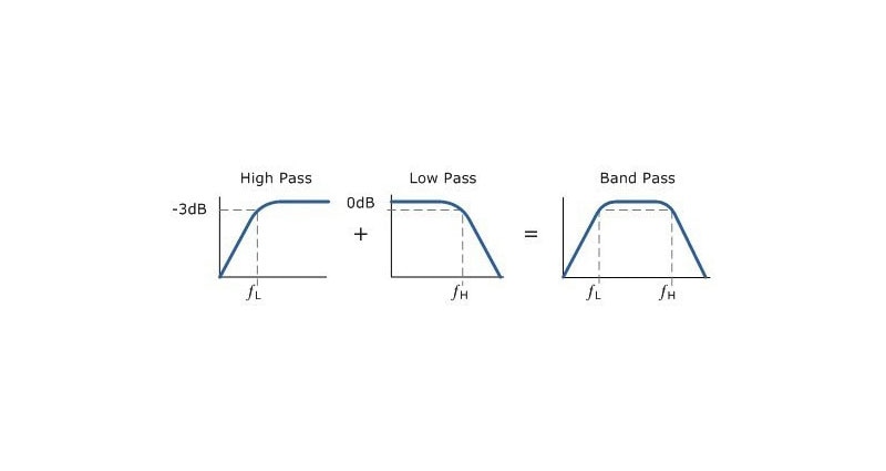
The type of RF filter used for the aforementioned applications are usually forms of bandpass filters, and we know that these filters can be created using a series of Inductors and Capacitors connected in weird and wonderful topologies. However, as much as these filters are respected and adaptable, due to intrinsic losses in the inductors and capacitors, they are unsuitable for applications above 500 MHz since their Q values just can’t get high enough to make them accurate for our uses.
RF MEMS Filters
This means we need to turn to Mechanical resonators like Quartz crystal and tuning fork resonators since they can achieve the Q values we need – well over 10,000. Quartz resonators are also known as piezoelectric resonators since Quartz is a piezoelectric material. This means that the material will create mechanical movement when a charge is applied and conversely will create a charge when mechanical stress is applied to it.
Geometric and material constraints are usually what dictate the quality factor and resonance frequencies of these mechanical piezoelectric resonators, and as such, to increase the range of frequencies these resonators can work at means that different materials and MEMS (Microelectromechanical – Systems) processes need to be employed to manufacture resonators to work at the frequencies needed. One piezoelectric material that has gained a lot of traction is Aluminium Nitride (AlN), mainly for its performance versus manufacturing efficiency.
BAW and SAW Resonators
The two main types of resonators we will be exploring are Bulk Acoustic Wave (BAW) Resonators and Surface Acoustic Wave (SAW) Resonators.
BAW Resonators
BAW resonators consist of a piezoelectric film placed between two metal electrodes. These electrodes induce an acoustic wave that propagates vertically along the “BULK” of the piezoelectric film and forms a standing wave between the electrodes.
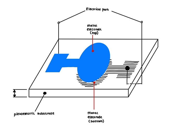
To keep the waves from escaping into the substrate there are a few configurations of BAW Filters: Membrane Type Resonators (MTR), Thin Film Bulk Acoustic Resonators (FBAR), and Solidly mounted Resonators (SMR).
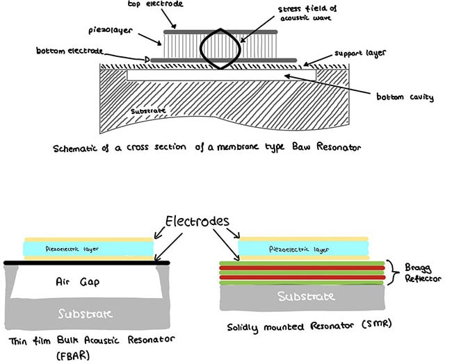
The FBAR and MTR devices use an air cavity under the active area, creating suspended membranes. Since the acoustic impedance of air is a factor of 10^5 lower than in typical solid materials, extremely little energy is radiated into the air, and 99.995% of the energy is reflected.
In the case of SMR devices, an acoustic Bragg Reflector is made by stacking multiple layers of alternating materials, all of varying reflective indexes to prevent the waves from escaping into the substrate.
At any of the interfaces between high and low impedance layers a large percentage of the wave will be reflected, and as the layers are spaced at a distance of λ/4 from each other, they will sum up with the correct phase. Using three pairs of mirror layers can result in a reflectivity that is good enough for any practical purpose if the impedance ratio, z = Z1/Z2, between the layers is high. A general relationship for the reflectivity of a mirror with N layer pairs of λ/4 thickness is 𝑟 = 1 − 𝑧2N.
- Design characteristics (what are the important factors to design such resonators?):
- The piezoelectric coupling coefficient Keff2 physically represents the energy conversion efficiency of the device and is defined by the distance between the series resonance and parallel resonance peaks. A piezo layer with too low coupling will not be able to make filters with the required bandwidth for mobile phone applications.
- The above equation is used to calculate the effective coupling coefficient using the series (fs) and parallel (fp) resonant frequency.
- Dielectric constant εr. The impedance level of a resonator is determined by the size of the resonator, the thickness of the piezo layer, and the dielectric constant. A higher dielectric constant εr enables one to reduce the resonator size.
- Acoustic velocity: A material with low acoustic velocity will result in thinner piezo layers and thus smaller devices.
- Temperature coefficient: Represents the amount of frequency shift when the temperature changes.
- For the BAW resonator, the figure of merit (FOM) is one of the most important parameters and can be defined as FOM = Keff2 × Q where Keff2 is the effective coupling coefficient, and Q is the quality factor. A larger Keff2 gives a wide bandwidth, which is desired for the 5G band.
Several material parameters need to be considered when making a BAW device:

- Resonant characteristics:
The resonant frequency of the filter is dictated by the acoustic velocity in the piezoelectric film and the thickness of the piezoelectric film.

Where v is the acoustic velocity, and d is the thickness of the piezoelectric film. The thickness of the electrode can affect resonance frequency too, and differing electrode thicknesses can generate frequency shifts that can be used to control the passband of the filter.
SAW Resonators
Unlike BAW filters, in SAW filters the acoustic wave and energy propagate along a single “Surface” of the substrate. As a result, the characteristics of the SAW resonator don’t rely on the substrate shape or thickness as much as BAW filters.
SAW resonators can be divided into two main types: one-port SAW resonators and two-port SAW resonators. The reflectors are located on both sides of the input and output IDT (interdigitated transducers) to contain the wave within a cavity and to create resonance.
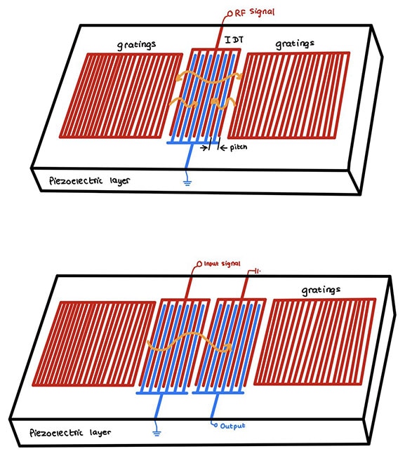
- Design characteristics (what are the important factors to design such resonators?):
The design characteristics of SAW filters are very similar to BAW filters in that coupling coefficients and acoustic velocity plays a powerful part in affecting their outputs. But more specifically, there are two main ways to affect the resonant frequency of SAW devices. To increase it, you can decrease the IDT bar’s line width and periodic spacing. This will use high-precision lithographic technology like ultraviolet or electron beam lithography. The other way is to use a substrate that has a higher acoustic velocity.
- Resonant characteristics:

where "pitch" is the distance between the middle of the two IDT fingers.
Lambda Wave Resonators
Lambda wave resonators use a structure that’s a combination of the SAW and FBAR resonators so they can utilize the advantages of both. This structure enables higher Quality factors and larger phase velocities.
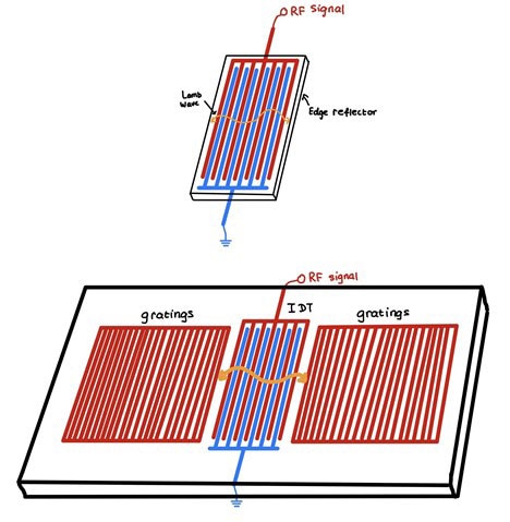
Floating edge reflectors or gratings are used to reflect and contain the acoustic wave.
- Design characteristics (what are the important factors to design such resonators):
There are three main boundary conditions; open-open, short, open, and short-short. Here the mechanical effect of the metallization is ignored. In other words, the metallization is assumed to be infinitely thin. The metallization slightly lowers the phase velocity, but this is usually ignored for simplicity.
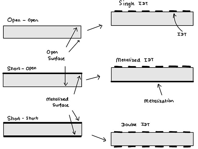
However, double IDTs are much more complicated to fabricate and as such are more expensive. So the most widely used configuration is the single IDT type and a thick AIN layer or an IDT floating BE type with a thin AIN layer.
- Resonant characteristics:
The resonant frequency of a Lambda wave resonator is the ratio of the phase velocity of the wave mode and the wavelength, i.e.

Conclusion
At frequencies of about 2 GHz or below, SAW filters are capable of excellent rejection of unwanted signals while maintaining flat amplitude responses across the passband frequency range. Although BAW filters can be fabricated for use at frequencies below 1.5 GHz, and well into the frequency range of SAW components, the larger sizes of BAW components at those lower frequencies result in lower yields of components per piezoelectric wafer, making it difficult to be cost-competitive with SAW filters.
However, since the dimensions of the IDT structure shrink with increasing frequency in SAW resonators, the challenges of producing SAW components with sufficiently small IDT dimensions to support those higher frequencies make it impractical. Because of this, SAW filters are not used for 5G applications since they just aren’t cost-effective compared to BAW filters at those frequencies. 5G applications nowadays use FBAR filters since they can operate in the 100 MHz to 10 GHz range. FBARs feature lower insertion loss – 0.3 to 0.5db – which equates to significantly lower current consumption and as a result extended battery usage for handheld devices.
This is by no means a comprehensive explanation of resonator filters, but I hope it serves as a high-level introduction to what MEMS RF Filters are and the underlying theories that allow them to work in the real world.

Have questions or comments? Continue the conversation on TechForum, DigiKey's online community and technical resource.
Visit TechForum


