Getting Headphone Leads to do “Double Duty”
It makes sense to visualize an antenna as a bidirectional transducer between electromagnetic energy in free space as defined by Maxwell’s equations and RF voltage and current confined to conductors or waveguides. But engineers are always striving to get a single path or interconnect to serve another unrelated function. A good example is the dual use of unshielded headphone wires as FM antennas.
The earliest portable AM/FM portable radios used two antennas: an internal long wire wound on a ferrite core for the lower frequency AM band (550-1600 kilohertz (kHz)) and a “whip” antenna about one to two meters (m) long for the FM band (88 to 108 MHz). As these radios got smaller and even more portable, some vendors eliminated their internal loudspeakers entirely, assuming their users would have headphones or wired earbuds instead.
Doing so also enabled a simple technique for eliminating the FM whip via a simple re-purposing of the headphone jack connection within the radio. The same approach was then extended to MP3 players which included an FM radio function (Figure 1). The technique is still employed by designers of many small electronic units with an FM radio.
 Figure 1: The SanDisk Clip Jam MP3 player measures just 55 mm × 35 mm × 10 mm thick and operates for 20 hours on a single charge; its integral FM radio uses the mandatory headphone lead as the antenna. (Image source: Lifewire)
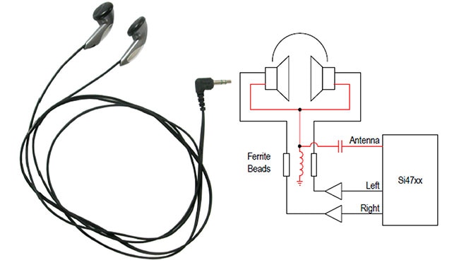
A basic unshielded headphone cable contains three conductors. The left and right audio channels are driven by a headphone amplifier onto the left and right audio conductors, while the common audio conductor is used for the audio return path. The same cable also functions as the FM antenna, using an inductor to block RF from ground while still allowing the audio signal to have a ground return. The circuit shown in Figure 2 is based around a Skyworks Solutions Si47xx AM/FM receiver.
 Figure 2 : The basic arrangement to enable the headphone wire to also function as an FM antenna requires just a few additional passive components. (Image source: Skyworks Solutions, Inc.)
A small capacitor allows antenna RF to pass to the receiver front-end while blocking audio from the antenna input. The ferrite beads provide a low-impedance audio path and a high-impedance RF path between the headphone amplifier and the headphones.
An actual circuit is somewhat more complicated, requiring some additional components for protection and voltage discharge, and to assure that signals only go where they should. The design in Figure 3 uses a Texas Instruments LM4910 headphone power amplifier configured for the role, along with any needed antenna signal connection/separation circuitry.
 Figure 3 : This LM4910 headphone amplifier is arranged via some additional passive components to use the headphone leads as an FM antenna. (Image source: Skyworks Solutions, Inc.)
The three-wire, left/right audio headphone jack receives the amplified audio signals from the LM4910, while the separated FM signal picked up by the headphone shield/ground is routed to the receiver front-end via a 100 picofarad (pF) capacitor. Diodes D1, D2, and D3 provide protection should any electrostatic discharge (ESD) exceed the rating of the headphone amplifier and the receiver.
It may seem that this technique should not be limited solely to FM band broadcast signals (88 to 108 MHz), but also be viable for AM radio (550 to 1550 kHz). In theory, it could work for the AM bands as long as the headphone wire has the right length. The reason it works for the FM band is because a headphone cable with a length between one and one-and-a-half meters is approximately half the wavelength of a broadcast-band FM signal, making it resonant and effective in that band. For the AM band, the headphone wire would need to be about 100 m long, which is obviously impractical.
Conclusion
Engineers have always sought to leverage an available resource such as a cable for multiple uses. The dual use of headphone leads as an FM antenna is a perfect example. As shown, all it takes is an appropriately configured power amplifier, a few passive components for routing, and diodes for protection.
References
Skyworks Solutions, AN383, “Si47XX Antenna, Schematic, Layout, and Design Guidelines”

Have questions or comments? Continue the conversation on TechForum, DigiKey's online community and technical resource.
Visit TechForum


