Boost the Efficiency and Lower the Noise of DC Regulated Circuits
One way we can provide an input voltage to a 24 volt direct current (DC) motor is to connect a nominal 24 volt supply to its terminals and flip the “on” switch. The motor will run perfectly well. But the problem with a nominal voltage supply is just that; it could, for example, go up to 38 volts or down to 15 volts. While such a voltage fluctuation might not damage a relatively hardy device like a DC motor, it would certainly affect its performance. The same can’t be said for sensitive automotive, avionics, or telecom applications. In these products, and many others, undervoltages or overvoltages could cause permanent damage.
A further challenge comes if the input supply doesn’t match that required by the DC motor. For example, a common DC supply voltage is 48 volts. Connecting that directly to a 24 volt motor is going to end in tears.
A DC voltage regulator offers us a straightforward solution. As the name suggests, the device can maintain a tightly regulated output from a variable input (within certain thresholds). So even if the input does vary between 38 and 15 volts, the regulator will provide a steady 24 volt output within just a few percentage points each way. Voltage regulators can also happily provide a different output from the input voltage, thus allowing us to safely power our 24 volt motor from a 48 volt supply.
The power of voltage regulation
There are many commercial options for voltage regulation. The simplest is the low dropout (LDO) linear regulator. An LDO is easy to design-in and requires few external components; it is also relatively inexpensive and compact. One notable downside is that the device is only able to provide an output that is lower than the input. This wouldn’t help us when our 24 volt supply drops below its nominal value.
The other potential downside of LDOs is poor efficiency. The device essentially uses a resistor divider network to regulate the voltage, so the larger the difference between the input and output voltages, the greater the internal power dissipation and the higher the temperature rise. If we used an LDO to, for example, regulate a 48 volt supply down to 24 volts, the regulator would operate at an efficiency of around 50%. In an age where we look to conserve energy whenever we can, such profligate burning of power is not acceptable (Figure 1.)
 Figure 1: The efficiency of an LDO is proportional to the ratio of the output voltage over the input voltage. (Image source: Analog Devices)
Improving on the LDO
Switching regulators bring greater efficiency to the voltage regulation task. The operating principles are complex, but regulation is essentially achieved by high-frequency switching of transistor pairs to periodically charge one or more inductors, which then dissipate their energy to the load, ready to be charged up again on the next cycle. Unlike an LDO, voltage regulation is not achieved by dividing the input voltage using a resistor network. This effectively eliminates most of the inefficiencies associated with the linear device.
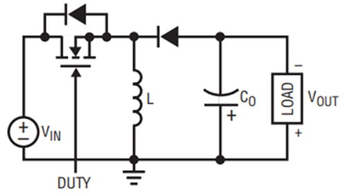
As a result, if we used a modern switching regulator to supply 24 volts from a 48 volt input, we could reasonably expect it to do so with an efficiency well above 90% (within some design constraints). Better yet, switching regulators can both step up (”boost”) and step down (“buck”) input voltages. Many devices can do both with seamless changes between the two modes. So even if the input voltage swings between low and high levels, the regulator will efficiently supply a steady 24 volts to keep our DC motor humming (Figure 2).
 Figure 2: The simplest form of a switching buck/boost voltage regulator comprises a transistor, two diodes, an inductor, and a capacitor. (Image source: Analog Devices)
There are a few downsides to switching regulators. They are complex, expensive, and require lots of external components that not only take up space but also require fairly advanced design skills to select them appropriately. Perhaps the biggest challenge comes from all that high-frequency switching. This switching not only generates electromagnetic interference (EMI) but can also impart a discernable ripple on the output voltage. Both can be mitigated, but not eliminated, by well-designed filter circuits.
Boosting efficiency
While switching regulators demonstrate excellent efficiency, they are not perfect. The main sources of power drain are DC losses while the transistors are conducting and switching losses when they flip states. Manufacturers have incorporated clever tricks into their products to enhance efficiency when operating in certain modes. For example, discontinuous conduction mode (DCM) prevents the regulator’s inductor current from reversing direction at low output currents. This helps improve the efficiency of light loads
Today’s switching voltage regulators regulate even when they don’t really need to, and in the process, expend unproductive energy. But there is one trick that has thus far been under-utilized. Consider the example of a 24 volt DC motor being fed with a nominal 24 volt supply. While we’ve seen that the supply can vary considerably, there will be plenty of times when it is at 24 volts, or at least very close to that. We could stop regulating the voltage when this happens and thereby improve efficiency by eliminating the conduction and switching losses, as well as other power losses incurred by the regulator.
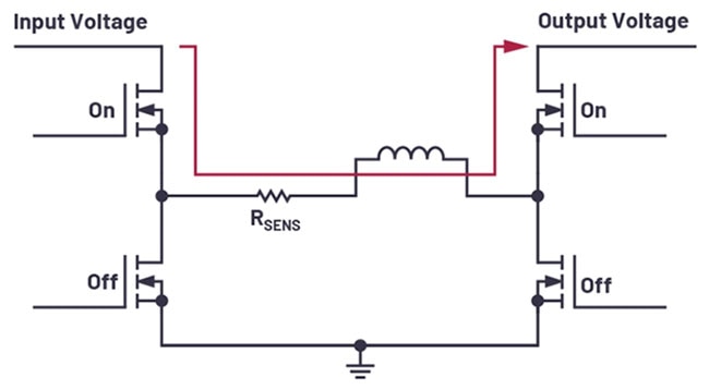
This is a technique commercialized by Analog Devices with its Pass-Thru mode. This has been incorporated into products such as the LT8210EFE buck-boost regulator (Figure 3). The regulator turns a 2.8 to 100 volt input into a 1 to 100 volt output and features two pairs of high and low-side transistors.
 Figure 3: In Pass-Thru mode, the input voltage flows through the LT8210 via the permanently switched-on high-side transistors. Efficiency is very high, and no noise is generated. (Image source: Analog Devices)
In Pass-Thru mode, the two high-side switches of the device are permanently on, allowing the unregulated voltage supply to flow directly through the device, while the two low-side switches are permanently off. Depending on the currents and voltages passing through the regulator, efficiencies of close to 100% are possible. Better yet, no EMI or output voltage ripple is generated while Pass-Thru is in operation.
Keeping things cool
You can set the LT8210’s Pass-Thru region by programming the low and high regulation thresholds. For example, it might be that you require a nominal 12 volt output for your load but know that it can safely tolerate an unregulated voltage of anything between 8 and 16 volts. You can therefore set the Pass-Thru mode for that range and benefit from very high efficiency when it occurs. For any supply voltage under 8 volts, the regulator will switch on to boost the voltage up to 8 volts, and for anything over 16 volts it will switch on to buck it to 16 volts (Figure 4).
 Figure 4: The Pass-Thru region can be programmed on the LT8210. Regulation then only occurs outside of this region. Note the increase in efficiency during operation in the Pass-Thru region. (Image source: Analog Devices)
Analog Devices also supplies a handy demonstration board, the DC2814A-C, that is based on the LT8210. The board operates from a 26 to 80 volt input and provides a 36 to 56 volt output, up to a maximum current of 2 amperes (A). The board can be used to show the benefits of Pass-Thru on parameters like component temperature (Figure 5, a and b).
 Figure 5 : Shown is the temperature profile of the DC2814A-C demonstration board (top, (a)) when regulating a 60 volt input down to a 56 volt output with a 2 A load current. The same demonstration board is shown (bottom, (b)) when operating in Pass-Thru mode with a 45 volt supply and a 2 A load current. (Image source: Analog Devices)
Conclusion
Switching regulators are an excellent choice for voltage regulation when high efficiency is important. But they still burn some power, and switching noise can be a challenge. Significant efficiency gains and noise-free operation can be achieved by taking advantage of Analog Device’s Pass-Thru feature. The more tolerant the load is of voltage fluctuations, the greater the potential gains.

Have questions or comments? Continue the conversation on TechForum, DigiKey's online community and technical resource.
Visit TechForum


