Why and How to Kickstart Cellular IoT Projects Using Microchip’s IoT Development Board
Contributed By DigiKey's North American Editors
2022-09-08
Cellular Internet of Things (IoT), a low power wide area network (LPWAN) technology, offers a clear and proven path to secure and robust IoT for applications ranging from smart cities to agriculture, and remote infrastructure monitoring. However, cellular IoT is a complex technology, daunting for inexperienced designers embarking on a project.
However, cellular IoT design challenges can be eased by basing projects on cellular development boards which use familiar general-purpose microcontrollers (MCU) and integrated design environments (IDEs). Backed up by libraries of open-source software and simple sensor connection, these development boards make it easier for the designer to get started with cellular IoT projects from hardware layout all the way up to sending data to the cloud.
This article briefly outlines the benefits of cellular IoT before explaining the design complexities that the technology can introduce. The article then describes how the use of cellular IoT development boards can eliminate much of this complexity. Finally, the article describes how to set up a Microchip Technology development board to send simple color and temperature data to the cloud.
What is cellular IoT?
Cellular IoT uses low-power cellular technology to connect IoT end devices (such as sensors and actuators) to the cloud. It is an LPWAN technology characterized by kilometer-plus range, high-density end-device support, and low throughput.
While other LPWAN technologies exist—notably LoRaWAN (see, “Accelerate LoRaWAN IoT Projects with an End-to-End Starter Kit”) and Sigfox—cellular IoT offers some key advantages, including:
- Future proofing: As a standard, the specification for cellular IoT is constantly under review and development.
- Scalability: Cellular IoT can support the rapid deployment of IoT through established cellular architecture.
- Quality of Service (QoS): Cellular IoT offers high reliability because it’s based on infrastructure that’s proven and mature in high-volume commercial applications.
- IP interoperability: End devices can be directly connected to the cloud without the need for expensive and complex gateways.
Designers need to factor in that with cellular IoT is there is an ongoing expense associated with data transfer. This is not the case with competing technologies such as LoRaWAN which use the unlicensed frequency spectrum. However, cellular IoT data costs are trending down due to competitive pressures and increased use of edge computing, reducing the volume of unremarkable data sent across the network.
Cellular IoT is governed by a telecom standard regulated and updated by the Third Generation Partnership Project (3GPP). Release 13 of the 3GPP’s standard extended its machine-to-machine (M2M) modem categories to allow for low-cost, low-power, and low-throughput modems suitable for IoT connectivity. Further releases to the standard have resulted in further enhancements to these IoT modems.
Wireless sensors equipped with cellular IoT modems can send data across kilometers to the cloud without the need for expensive and complex gateways, along with the security and QoS for which cellular is known.
The difference between LTE-M and NB-IoT
Cellular IoT comes in two forms, LTE category M1 (LTE-M) and narrow band IoT (NB-IoT). Both types are designed for use with resource-constrained, often battery-powered devices that are typical of the IoT and Industrial IoT (IIoT). Because IoT modems connect to established cellular infrastructure, each requires its own subscriber identity module (SIM).
LTE-M is based on stripped-down LTE (“4G”) technology. It supports secure communication, ubiquitous coverage, and high system capacity. Its ability to operate as a full-duplex system over a relatively wide bandwidth (1.4 megahertz (MHz)) improves latency and throughput compared with NB-IoT. The raw data throughput is 300 kilobits per second (Kbits/s) downlink and 375 Kbits/s uplink. The technology is suitable for secure end-to-end IP connections, and mobility is supported by LTE cell handover techniques. LTE-M is suitable to mobile applications such as asset tracking or healthcare.
NB-IoT is primarily designed for energy efficiency and for better penetration into buildings and other RF unfriendly areas. Unlike LTE-M, it is not based on the LTE physical layer (PHY). Modem complexity is even less than that of an LTE-M device, as NB-IoT uses a 200 kilohertz (kHz) bandwidth. While raw data throughput is a modest 60/30 Kbits/s, range is better than LTE-M. NB-IoT is suited to static applications such as smart meters that might be obscured by walls.
Commercial cellular IoT modems
A range of commercial LTE-M/NB-IoT modems is now available. One example is the Monarch 2 GM02S module from Sequans. The device supports a single stock keeping unit (SKU) RF front-end suitable for 20 of the global LTE bands. It is supplied in a compact LGA module measuring 16.3 x 17 x 1.85 millimeters (mm). The module meets the requirements of 3GPP Release 14/15. Powered from a single supply of 2.2 to 5.5 volts, the modem is capable of a maximum transmit power of +23 decibels referenced to 1 milliwatt (mW) (dBm).
The GM02S supports an external SIM and eSIM as well as integrated SIMs. A 50 ohm (Ω) antenna interface is included. The device is supplied with an LTE-M/NB-IoT software stack and Sequan’s Cloud Connector software for ease of connection to commercial cloud platforms (Figure 1).
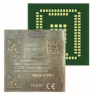 Figure 1: Sequans’ GM02S LTE-M/NB-IoT modem comes in a compact package and with a mature software stack. (Image source: Sequans)
Cellular IoT design challenges
While the GM02S modem is a highly integrated device supplied with a software stack and cloud connectivity, like all commercial modems, there is still considerable development work required before an IoT application is seamlessly sending data over kilometers to the cloud.
The modem is designed solely to look after communication between the end-device and the base station. A separate supervisory and application processor is needed to control the modem while also running the sensor application software. In addition, the designer also needs to consider the antenna circuit(s), power supply, and equipping an end-device with a SIM to ensure seamless connectivity with the cell network (see, “How to Use Multiband Embedded Antennas to Save Space, Complexity, and Cost in IoT Designs”).
Beyond the hardware design, some coding skills are needed to get a cellular module to connect to the network and receive/transmit data. If the design uses an external application MCU, it typically communicates with the cellular module using a UART serial link (although other I/O interfaces are also used). AT (“attention”) commands are the standard means of controlling a cellular modem. The commands comprise a series of short text strings that can be combined to produce operations such as dialing, hanging up, and changing the parameters of the connection.
There are two types of AT commands: Basic commands are those that don’t start with “+”. “D” (Dial), “A” (Answer), “H” (Hook control), and “O” (Return to online data state) are examples. Extended commands are those that do start with “+”. For example, “+CMGS” (Send SMS message), “+CMGL” (List SMS messages), and “+CMGR” (Read SMS messages) (see “Use a Cellular Module to Connect a Maker Project to the IoT”).
These hardware and software considerations bring complexity to cellular IoT that could slow progress with less-experienced designers. Fortunately, application MCU and cellular IoT modem makers have now gotten together to offer hardware and software design tools that make it much easier to take advantage of this important LPWAN technology.
Eliminating complexity with IoT development boards
Tackling the challenges of cellular IoT design is considerably eased by basing a prototype on a purpose-designed development board. The development board hardware typically includes an antenna, a power source, a SIM with some free data allowance, an application processor, and tuning networks to ensure good RF performance. This gives designers a solid hardware head-start for their project and allows them to focus on application development. With the right choice of development board, the application development can even be conducted in a familiar IDE.
One example of a popular cellular IoT development board is the EV70N78A AVR-IoT Cellular Mini Development Board from Microchip. This is a hardware platform based around the popular Microchip AVR128DB48 MCU, and the Sequans Monarch 2 GM02S cellular module detailed above. The MCU is an 8-bit, 24 MHz device. It has 128 kilobytes (Kbytes) of flash, 16 Kbytes of SRAM, 512 bytes of EEPROM, and comes in a 48-pin package.
The development board also integrates an ATECC608B secure element; once connected to an LTE-M or NB-IoT network, the ATECC608B is used to authenticate the hardware with the cloud to uniquely identify every board.
To make things even easier for the designer, the Microchip development board also includes an activation-ready Truphone SIM card with 150 megabytes (Mbytes) of data.
The development board features five user LEDs, two mechanical buttons, a 32.768 kHz crystal, color and temperature sensors, an Adafruit Feather compatible edge-connector, a Qwiic I2C connector, an on-board debugger, a USB port, battery and external input power options, and an MCP73830 Li-ion/Li-po battery charger with charge status LED (Figure 2).
 Figure 2: The AVR-IoT Cellular Mini Development Board is based on the AVR128DB48 MCU and comes complete with a SIM card and 150 Mbytes of data. (Image source: Microchip Technology)
Starting a cellular IoT project
The purpose of cellular IoT is to wirelessly connect IoT end-devices such as sensors and actuators so their data can be sent over kilometers to the cloud. On the Microchip development board, the MCU is preloaded with a firmware image forming a demo application that lets users quickly connect and send data from the onboard temperature and color sensors to a cloud-based sandbox (hosted by AWS).
To get the hardware ready for development, it’s simply a case of activating and inserting the SIM card, connecting the external antenna to the board, connecting the debug USB-C port on the board to the PC, scanning the QR code on the bottom of the board or opening the mass-storage device, and following the CLICK-ME.HTM to the kit web page.
A Microchip IoT Provisioning Tool, available from Github, provides an easy-to-use solution for configuring an AVR-IoT Cellular Mini to the selected cloud provider, setting the network provider, and selecting cellular frequency bands. (For the sandbox demo firmware to work, the development board must be provisioned for the AWS Microchip sandbox.)
Once developers have gained some confidence with the demo application, they can start to build their own application using the development board’s full Arduino IDE support. This support is based on an AVR IoT cellular Arduino library hosted on Github. The library is built on top of the open-source DxCore (Figure 3).
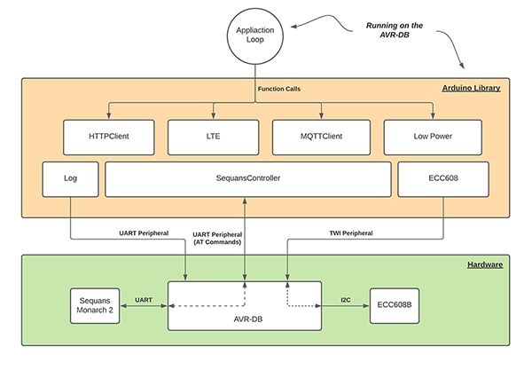 Figure 3: The AVR IoT cellular IoT library (orange) includes software modules for programming and controlling the development board (shown in simplified form in green). (Image source: Microchip Technology)
The on-board debugger (PKOB nano) supplies full programming support for the Arduino IDE. There’s no need for any external tools, and it also provides access to a serial port interface (serial-to-USB bridge) and two logic analyzer channels (debug GPIO). The on-board debugger on the AVR IoT Cellular Mini board appears as a human interface device (HID) on the host computer’s USB subsystem. For more ambitious projects, the development board’s Qwiic and Feather compatible edge connectors allow for easy expansion from a wide selection of add-on boards from Sparkfun and Adafruit (Figure 4).
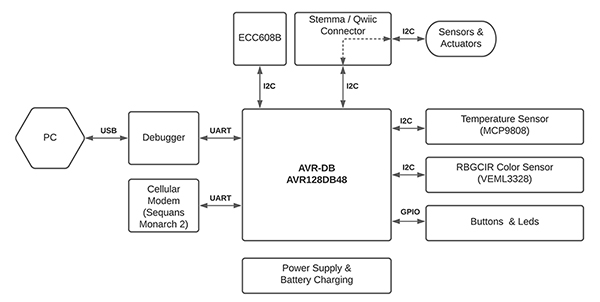 Figure 4: This AVR IoT development board block diagram shows that the connection to the host PC is via the debugger’s USB link, while programming of the application MCU is via the debugger’s UART link. Note the connection between the application MCU and the cellular modem is also via UART. (Image source: Microchip Technology)
Getting started on application programming requires downloading and installing the Arduino IDE and DxCore. Next, the Arduino IDE needs to be configured to allow the AVR IoT cellular Arduino library to run (List 1).
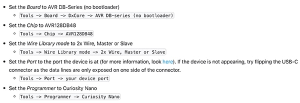 List 1: Configuration of the Arduino IDE to allow the AVR IoT cellular Arduino library to run. (Code source: Microchip Technology)
Once the IDE is configured the library can be installed. When this is done, several library examples for the development board can be accessed. Designers familiar with the Visual Studio Code IDE can use it for AVR IoT development, providing they install the Arduino plugin. Arduino application code developed in either IDE is ported to the development board’s MCU via the on-board debugger.
Making power measurements
Cellular IoT is designed to run at low power to extend the life of battery-powered IoT end devices. It’s therefore important to optimize the application code toward minimal power consumption.
On the Microchip development board, power to all the board parts is connected through five cut-straps. These are also intended for current measurement purposes. To measure power on the desired circuit, it is a case of cutting the strap and connecting an ammeter across the holes (Figure 5).
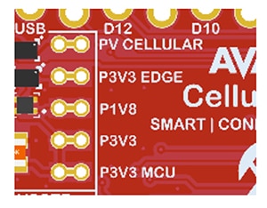 Figure 5: Cut-straps on the AVR IoT development board can be used to measure power consumption for key circuits. (Image source: Microchip Technology)
The development board also has a system voltage measurement circuit using its MIC94163 switch and a voltage divider connected to an ADC pin on the MCU, enabling on-demand measurement and preventing power leakage through the voltage divider. To measure the system voltage, follow these steps:
- Configure the voltage reference for the ADC.
- Set the MCU GPIO system voltage measurement enable pin (PB3) high to enable the voltage divider.
- Set the MCU ADCO system voltage measurement pin (PE0) as the input for the ADC.
- Run a single-ended analog-to-digital conversion (ADC).
- Calculate the voltage using the equation: V = ADC result x VREF x 4/ADC resolution.
Finally, it is also simple to measure the supply voltage by following these steps:
- Configure the voltage reference for the ADC.
- Select VDD or VDDIO2 as the positive input to the ADC. (VDD and VDDIO2 are available internal input channels to the MCU’s ADC.)
- Run a single-ended ADC conversion.
- Calculate the voltage using the equation: V = ADC result x VREF x 10/ADC resolution.
Conclusion
Cellular IoT is a popular LPWAN with increasing commercial potential. However, designing cellular IoT-powered end devices requires both hardware and software expertise. To enable designers, new cellular IoT development boards, such as Microchip’s EV70N78A AVR-IoT Cellular Mini Development Board, offer a quick prototyping route.
The development board uses a high-end LTE-M/NB-IoT modem and a popular Microchip MCU. Application code development is simplified using the Arduino or Visual Studio Code IDE.

Disclaimer: The opinions, beliefs, and viewpoints expressed by the various authors and/or forum participants on this website do not necessarily reflect the opinions, beliefs, and viewpoints of DigiKey or official policies of DigiKey.


