When and How to Use Bridgeless Totem-Pole Power Factor Correction
Contributed By DigiKey's North American Editors
2022-09-28
High power factor (PF) and high efficiency are key requirements for AC-DC power supplies used in servers, networking, 5G telecommunications, industrial systems, electric vehicles, and a range of other applications. However, the challenge for power supply designers is to simultaneously meet the PF and electromagnetic compatibility (EMC) requirements of standards such as IEC 61000-3-2, as well as the latest 80 PLUS Titanium efficiency standard from EnergyStar. The latter calls for a minimum of 90% efficiency at 10% load and 94% efficiency at full load. A conventional boost PF correction (PFC) topology can deliver high PF and good EMC but includes a relatively inefficient diode bridge, making it difficult to meet the expected efficiency standards.
Replacing the diode bridge with a bridgeless totem-pole PFC topology delivers both high PF and high efficiency. However, this introduces greater complexity since the topology includes two control loops: a slow loop operating at the line frequency for rectification, and a high-frequency loop for the boost section. Designing two control loops from scratch is a time-consuming process that can delay time to market and result in a solution that is more costly and larger than necessary.
To meet these challenges, designers can instead turn to PFC controller ICs optimized for use in bridgeless totem-pole PFC designs. These controllers have internally compensated digital loops, can implement cycle-by-cycle current limit without needing a Hall effect sensor, and can be used with silicon MOSFETs or wide bandgap (WBG) switching devices, such as silicon carbide (SiC) or gallium nitride (GaN). The resulting PFC can operate with inputs from 90 to 265 volts AC and with efficiencies up to 99%.
This article briefly reviews the industry standards that AC-DC power supplies are required to meet, compares the performance of various PFC topologies, and identifies when a bridgeless totem-pole PFC is the best choice. It then presents a controller IC from onsemi optimized for use in bridgeless totem-pole PFC, along with support components, an evaluation board, and design suggestions to speed the development process.
Efficiency can be complicated
Power supply efficiency is more complicated than it first appears as it includes both AC and DC components. Simple efficiency is the ratio of the input power to the output power. However, the input power for a typical AC-DC power supply is not purely sinusoidal, resulting in a difference between the in-phase and out-of-phase power drawn from the ac mains. That difference is recognized as the PF. For a complete description of the efficiency of an AC-DC power supply, both the DC efficiency and the PF need to be included. To make it more challenging, efficiency curves are not flat: efficiency and PF can vary with parameters such as the input voltage and the output load.
To account for these variables, efficiency standards like EnergyStar define efficiency at various load levels and at different input voltages, along with a requirement for PF (Table 1). The highest level, called “80 PLUS Titanium,” specifies a minimum efficiency for 115 volts AC input of 90% at both 10% and 100% of rated load, 94% efficiency at 50% of rated load, plus a PF of ≥95% at 20% of rated load. Higher efficiencies are required for 230 volts AC input. In addition, power supplies are expected to meet IEC 61000-3-2 which places limits on the power line harmonics.
 Table 1: Performance standards like EnergyStar include requirements for PF as well as efficiency. (Table source: onsemi)
There are two common approaches to PFC: a boost converter based on diode rectification; and a more complex, more efficient totem-pole topology based on active rectification (Figure 1). A boost converter PFC can meet basic PF and efficiency requirements, but is not adequate for stringent requirements such as 80 PLUS Titanium. For example, in a boost PFC, there can be losses of 2% in the DC-DC stage, and losses of 1% in the line rectification and PFC stage (this can rise to nearly 2% at low line operation). With nearly 4% losses at low line, it’s challenging to meet the 80 PLUS Titanium requirement of 96% efficiency with an input of 230 Volts AC and 50% loading. In applications that demand the highest levels of efficiency, the losses in the PFC stage can be reduced by replacing the diode rectifiers with synchronous rectification.
 Figure 1: Two common PFC topologies include a basic boost converter (left) and a totem pole (right). (Image source: onsemi)
In the totem-pole PFC above, Q3 and Q4 are the slow leg that implements synchronous rectification at line frequency, while Q1 and Q2 form the fast leg that boosts the rectified voltage to a higher level, such as 380 volts DC. While it’s possible to implement a totem pole using low-on-resistance (RON) MOSFETs for Q1 and Q2, the high-frequency switching losses due to the reverse recovery of the MOSFETs reduce efficiency. As a result, in many totem-pole PFC designs, the Q1 and Q2 silicon MOSFETs are replaced with SiC or GaN power switches that have little or no reverse recovery losses.
Optimized control
Another decision when designing a PFC is the selection of the control technique. PFCs can operate in continuous conduction mode (CCM), discontinuous (DCM), or critical conduction (CrM) modes. These modes differ by the operating characteristics of the boost inductor (L1 in Figure 1). CCM makes the best use of the inductor and keeps conduction and core losses low, but CCM is hard switching and has higher dynamic losses. DCM can be efficient for low-power operation, but suffers from relatively high peak and rms currents, resulting in higher conduction and core losses in the inductor.
CrM can provide higher efficiency in designs up to a few hundred watts. With CrM, changes in line voltage and load current are monitored, and the switching frequency is adjusted to operate between CCM and DCM. CrM has low turn-on losses, and it limits the peak current to twice the average current, maintaining conduction and core losses at a reasonable level (Figure 2).
 Figure 2: CrM PFC boost inductor peak current (Ipk) is limited to double the input line current. (Image source: onsemi)
However, there are some challenges associated with using CrM:
- It’s a hard−switching topology, and the forward recovery of the boost device adds some losses and can cause an output voltage overshoot.
- At light loads, it runs at very high frequencies, increasing switching losses and reducing efficiency.
- There are four active devices to control, plus the need to detect zero current in the PFC inductor and regulate the output voltage.
CrM can be implemented using in-circuit sensors along with a microcontroller (MCU) to perform the complex control algorithms. Coding the algorithms to account for the performance challenges delineated above is risky and time-consuming, potentially delaying time to market.
No-code totem poles
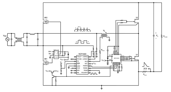
To address these concerns, designers can turn to the NCP1680ABD1R2G mixed-signal controller from onsemi that provides an integrated and no-code CrM totem-pole PFC solution. The SOIC-16 packaged controller is AEC-Q100 qualified for automotive applications and features low-loss, low-cost, resistive current sensing, and implements cycle-by-cycle current limiting protection without the need for a Hall effect sensor (Figure 3). The internally compensated digital voltage control loop optimizes performance through the entire load range, simplifying PFC design.
 Figure 3: The NCP1680 CrM controller uses low-cost and efficient resistive current sensing (ZCD in the lower right-hand corner of the schematic). (Image source: onsemi)
High-speed gate driver
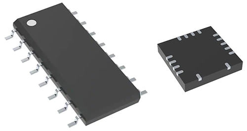
The NCP1680 controller can be paired with onsemi's 4 x 4 millimeter (mm) 15-pin QFN packaged NCP51820 high-speed gate driver. It is designed for use with gate injection transistor (GIT) GaN high electron mobility transistors (HEMTs) and enhancement mode (e-mode) GaN power switches in half-bridge topologies (Figure 4).
 Figure 4: The NCP1680 controllers (left) can be paired with the NCP51820 high-speed gate driver (right) to drive GaN power devices in a totem-pole PFC. (Image source: onsemi)
For example, the NCP51820AMNTWG features short and matched propagation delays, as well as a common-mode voltage range for the high-side drive of -3.5 volts to +650 volts (typical). The driver stages have dedicated voltage regulators to protect the gates of GaN devices from voltage stress. The NCP51820 gate drivers include independent undervoltage lockout (UVLO) and thermal shutdown protection.
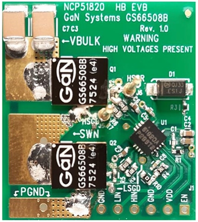
To speed time to market, designers can use the NCP51820GAN1GEVB evaluation board (EVB). This EVB helps designers explore the performance of the NCP51820 drivers to efficiently drive two GaN power switches in a totem-pole configuration. The NCP51820GAN1GEVB is designed using a four-layer, 1310 thousandths of an inch (mil) x 1180 mil printed circuit (PC) board. It includes the NCP51820 GaN driver and two e-mode GaN power switches in a half-bridge configuration (Figure 5).
 Figure 5: The NCP51820GAN1GEVB EVB includes an NCP51820 driver and two E−mode GaN switches in a half-bridge configuration. (Image source: onsemi)
Design suggestions
There are some simple design suggestions designers can follow to realize the best performance when using these ICs. For example, to prevent noise coupling into the signal path and accidentally triggering the NCP51820 gate driver, onsemi recommends that the control signals (PWMH and PWML) from the NCP1680 be filtered directly at the input of the gate driver IC. A 1 kiloohm (kΩ) resistor and either a 47 or 100 picofarad (pF) capacitor placed directly at the pin of the driver can provide adequate filtering (Figure 6).
 Figure 6: Filtering of the PWMH and PWML control signals from the NCP1680 right at the input of the NCP51820 gate driver IC can prevent noise effects, such as the accidental triggering of the NCP51820. The filtering is accomplished here using 1 kΩ resistors (center left) and 47 pF capacitors (center right). (Image source: onsemi)
The skip/standby mode of the NCP1680 enables very good no-load and light-load performance, but it must be externally triggered by pulsing the PFCOK pin or grounding the SKIP pin and interfacing with the NCP13992 resonant mode controller (Figure 7). The component values for the interface circuitry should be similar to those found on the NCP1680 EVB. Under normal operation, the PFCMODE pin on NCP13992 resonant mode controller is the same as the VCC bias voltage of the controller. It pulses to ground when the converter enters skip mode. To enter skip mode, the PFCOK pin must be below 400 millivolts (mV) for over 50 microseconds (μs).
 Figure 7: Example of the external triggering circuit needed to invoke skip/standby mode in the NCP1680. (Image source: onsemi)
Conclusion
Simultaneously meeting the efficiency, EMC, and PF requirements of the latest EnergyStar standards, such as 80 PLUS Titanium, can be challenging using a typical boost converter PFC topology. Designers can instead turn to a totem-pole PFC topology. As shown, the use of the NCP1680 mixed signal controller, along with supporting components from onsemi—such as the NCP51820 gate driver, an evaluation board, as well as some design best practices—lets designers quickly implement a CrM totem-pole PFC solution while meeting required standards.
Recommended Reading

Disclaimer: The opinions, beliefs, and viewpoints expressed by the various authors and/or forum participants on this website do not necessarily reflect the opinions, beliefs, and viewpoints of DigiKey or official policies of DigiKey.


