Use Multiprotocol Wireless Modules to Simplify IoT Product Design and Certification
Contributed By DigiKey's North American Editors
2023-06-29
Wireless connectivity allows designers to turn dumb products into smart, integrated elements of the Internet of Things (IoT) that can send data to the cloud for artificial intelligence (AI)-based analysis while allowing devices to receive over-the-air (OTA) instructions, firmware updates, and security enhancements.
But adding a wireless link to a product is not trivial. Before the design phase can even start, designers need to choose a wireless protocol, which can be daunting. For example, several wireless standards operate in the popular, license-free 2.4 gigahertz (GHz) spectrum. Each one of these standards represents a trade-off in terms of range, throughput, and power consumption. Selecting the best one for a given application requires careful evaluation of its requirements against a protocol’s characteristics.
Then, even with highly integrated modern transceivers, designing the radio frequency (RF) circuit is a challenge for many design teams, leading to cost and schedule overruns. Moreover, an RF product will need to be certified for operation, which in itself can be an involved, complex, and time-consuming process.
One solution is to base the design on a certified module that uses a multiprotocol system-on-chip (SoC). This eliminates the complexity of RF design with discrete components and allows for flexibility in the choice of wireless protocol. This module approach presents designers with a drop-in wireless solution, making it much easier to integrate wireless connectivity into products and pass certification.
This article considers the benefits of wireless connectivity, looks at the strengths of some key 2.4 GHz wireless protocols, briefly analyzes hardware design issues, and introduces a suitable RF module from Würth Elektronik. The article also discusses the certification process required to satisfy global regulations, considers application software development, and introduces a software development kit (SDK) to help designers get started with the module.
The advantages of multiprotocol transceivers
No single short-range wireless sector dominates because each makes trade-offs to satisfy their target applications. For example, greater range and/or throughput comes at the cost of increased power consumption. Other important factors to consider are interference immunity, mesh networking capability, and Internet protocol (IP) interoperability.
Of the various established short-range wireless technologies, there are three clear leaders: Bluetooth Low Energy (Bluetooth LE), Zigbee, and Thread. They share some similarities due to a shared DNA from the IEEE 802.15.4 specification. That specification describes physical (PHY) and media access control (MAC) layers for low data rate wireless personal area networks (WPANs). The technologies generally operate at 2.4 GHz, although there are some sub-GHz variants of Zigbee.
Bluetooth LE is suited to IoT applications such as smart home sensors where data transmission rates are modest and occur infrequently (Figure 1). Bluetooth LE’s interoperability with the Bluetooth chips hosted by most smartphones is also a big advantage for consumer-oriented applications such as wearables. Key downsides to the technology are the requirement for an expensive and power-hungry gateway to connect to the cloud and clunky mesh networking capabilities.
 Figure 1: Bluetooth LE is well suited to smart home sensors such as cameras and thermostats. Its interoperability with smartphones simplifies the configuration of compatible products. (Image source: Nordic Semiconductor)
Zigbee is also a good choice for low power and low throughput applications in industrial automation, commercial, and the home. Its throughput is lower than Bluetooth LE, while its range and power consumption is similar. Zigbee is not interoperable with smartphones, nor does it offer native IP capability. A key advantage of Zigbee comes from it being designed from the ground up for mesh networking.
Thread, like Zigbee, operates using the IEEE 802.15.4 PHY and MAC and has been designed to support large mesh networks of up to 250 devices. Where Thread differs from Zigbee is through its use of 6LoWPAN (a combination of IPv6 and low-power WPANs), making connectivity with other devices and the cloud straightforward, albeit via a network edge device called a border router. (See, “A Brief Guide to What Matters in Short-Range Wireless Technologies”.)
While standards-based protocols dominate, there is still a niche for 2.4 GHz proprietary protocols. Though they limit connectivity to other devices equipped with the same manufacturer’s chip, such protocols can be finely tuned to optimize power consumption, range, interference immunity, or other important operational parameters. An IEEE 802.15.4 PHY and MAC is perfectly capable of supporting 2.4 GHz proprietary wireless technology.
The popularity of these three short-range protocols and the flexibility offered by 2.4 GHz proprietary technology makes it difficult to choose the right one to suit the widest set of applications. Previously, a designer had to choose one wireless technology and then redesign the product if there was a demand for a variant using a different protocol. But because the protocols use PHYs based on a similar architecture and operate in the 2.4 GHz spectrum, many silicon vendors offer multiprotocol transceivers.
These chips allow a single hardware design to be reconfigured for several protocols simply by uploading new software. Better yet, the product could be shipped with multiple software stacks, with switching between each supervised by a microcontroller unit (MCU). This could allow, for example, Bluetooth LE to be used to configure a smart home thermostat from a smartphone before the device switches protocols to join a Thread network.
Nordic Semiconductor's nRF52840 SoC supports Bluetooth LE, Bluetooth mesh, Thread, Zigbee, IEEE 802.15.4, ANT+, and 2.4 GHz proprietary stacks. The Nordic SoC also integrates an Arm® Cortex®-M4 MCU—which looks after the RF protocol and application software—as well as 1 megabyte (Mbyte) of flash memory and 256 kilobytes (Kbytes) of RAM. When running in Bluetooth LE mode, the SoC offers a maximum raw data throughput of 2 megabits per second (Mbits/s). The transmit current draw off its 3-volt DC input supply is 5.3 milliamps (mA) at 0 decibels referenced to 1 milliwatt (dBm) of output power, and the receive (RX) current draw is 6.4 mA at a raw data rate of 1 Mbit/s. The nRF52840’s maximum transmit power is +8 dBm and its sensitivity is -96 dBm (Bluetooth LE at 1 Mbit/s).
The importance of good RF design
While wireless SoCs such as Nordic’s nRF52840 are very capable devices, it still requires considerable design skill to maximize its RF performance. In particular, the engineer needs to consider factors such as power supply filtering, external crystal timing circuits, antenna design and placement, and crucially, impedance matching.
The key parameter that differentiates a good RF circuit from a poor one is its impedance (Z). At high frequencies, such as the 2.4 GHz used by a short-range radio, the impedance at a given point on an RF trace is related to the characteristic impedance of that trace, which in turn depends on the printed circuit (pc) board substrate, dimensions of the trace, its distance from the load, and the load’s impedance.
It turns out that when the load impedance—which for a transmitting system will be the antenna and for a receiving system is the transceiver SoC—is equal to the characteristic impedance, the measured impedance remains the same at any distance along the trace from the load. As a result, line losses are minimized, and maximum power is transferred from the transmitter to the antenna, thereby boosting robustness and range. That makes it good design practice to build a matching network that ensures an RF device’s impedance is equal to the pc board trace’s characteristic impedance. (See, “Bluetooth 4.1, 4.2 and 5 Compatible Bluetooth Low Energy SoCs and Tools Meet IoT Challenges (Part 2)”.)
The matching network comprises one or more shunt inductors and series capacitors. The designer’s challenge is to choose the best network topology and component values. Manufacturers often offer simulation software to help with matching circuit design, but even after following good design rules, the resulting circuit can often exhibit disappointing RF performance, lacking range and reliability. This leads to more design iterations to revise the matching network (Figure 2).
") Figure 2: The Nordic nRF52840 requires external circuitry to exploit its functionality. External circuits include input voltage filtering, support for external crystal timing, and connected to the SoC’s antenna (ANT) pin, impedance matching circuitry between the SoC and an antenna. (Image source: Nordic Semiconductor)
Figure 2: The Nordic nRF52840 requires external circuitry to exploit its functionality. External circuits include input voltage filtering, support for external crystal timing, and connected to the SoC’s antenna (ANT) pin, impedance matching circuitry between the SoC and an antenna. (Image source: Nordic Semiconductor)
The advantages of a module
There are some advantages to designing a short-range wireless circuit using discrete components, notably lower bill-of-material (BoM) costs and space savings. However, even if the designer follows one of the many excellent reference designs from SoC suppliers, other factors—such as component quality and tolerances, board layout and substrate characteristics, and end-device packaging—can dramatically affect RF performance.
An alternative approach is to base the wireless connectivity around a third-party module. The modules are fully assembled, optimized, and tested solutions that enable “drop-in” wireless connectivity. In most cases, the module will already be certified for use in global markets, saving the designer the time and money needed to pass RF regulation certification.
There are some downsides to module use. These include increased expense (depending on volume), larger end-product size, reliance on a single vendor and its ability to ship in volume, and (sometimes) a reduced number of accessible pins relative to the SoC upon which the module is based. But if design simplicity and faster-time-to-market outweigh these downsides, then a module is the answer.
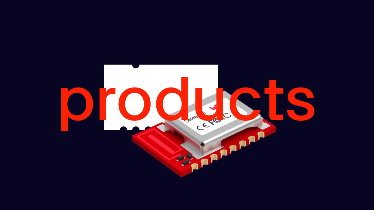
One example that uses the Nordic nRF52840 at its heart is Würth Elektronik’s Setebos-I 2.4 GHz radio module 2611011024020. The compact module measures 12 × 8 × 2 millimeters (mm), has a built-in antenna, a cover to minimize electromagnetic interference (EMI), and comes with firmware to support Bluetooth 5.1 as well as proprietary 2.4 GHz protocols (Figure 3). As described above, the SoC at the heart of the module is also capable of supporting Thread and Zigbee—with the addition of appropriate firmware.
 Figure 3: The Setebos-I 2.4 GHz radio module comes in a compact form factor, has a built-in antenna, and comes with a cover to limit EMI. (Image source: Würth Elektronik)
The module accepts a 1.8-to-3.6-volt input, and when in sleep mode, draws just 0.4 microamperes (µA). Its operating frequency covers the Industrial, Scientific, and Medical (ISM) band, which is centered on 2.44 GHz (2.402 to 2.480 GHz). In ideal conditions, with 0 dBm output power, the line-of-site range between the transmitter and the receiver is up to 600 meters (m), and the maximum Bluetooth LE throughput is 2 Mbits/s. The module features a built-in quarter wavelength (3.13-centimeter (cm)) antenna, but it is also possible to boost the range by connecting an external antenna to the aforementioned ANT terminal on the module (Figure 4).
 Figure 4: The Setebos-I 2.4 GHz radio module includes a pin for an external antenna (ANT) to extend the radio’s range. (Image source: Würth Elektronik)
The Setebos-I radio module provides access to the nRF52840 SoC’s pins via solder pads. Table 1 lists the function of each module pin. Pins “B2” to “B6” are programmable GPIOs that are useful for connecting sensors such as temperature, humidity, and air quality devices.
|
Table 1: Shown are the Setebos-I 2.4 GHz radio module’s pin designations. LED outputs can be used to indicate radio transmission and reception. (Image source: Würth Elektronik)
Short-range wireless product certification
While the 2.4 GHz band is a license-free spectrum allocation, radio devices operating in the band are still required to meet local regulations such as those dictated by the U.S. Federal Communications Commission (FCC), European Declaration of Conformity (CE), or Telecom Engineering Center (TELEC) in Japan. Passing the regulations requires submitting a product for testing and certification, which can be time-consuming and expensive. If the RF product fails any part of the test, a completely new submission must be made. If the module is going to be used in Bluetooth mode, it will also need a Bluetooth listing from the Bluetooth Special Interest Group (SIG).
Certification for the module doesn’t automatically confer certification onto the end product using the module. But it does typically turn the certification for end products into a paperwork exercise rather than an extensive retesting task—providing they don’t use additional wireless devices such as Wi-Fi. The same is generally true when obtaining the Bluetooth listing. Once certified, products using the module carry a label indicating FCC, CE, and other relevant ID numbers (Figure 5).
 Figure 5: Example of an ID label appended to the Setebos-I module to show that it has passed CE and FCC RF certification. Certification can generally be inherited by the end product without retesting through some simple paperwork. (Image source: Würth Elektronik)
Module makers typically go to the extent of obtaining RF certification (and Bluetooth listing if appropriate) for their modules for the regions in which they intend to sell the products. Würth Elektronik has done this for the Setebos-I radio module, though it must be used with the factory firmware. In the case of Bluetooth operation, the module is pre-certified, provided it is used with Nordic’s S140 Bluetooth LE factory stack or a stack supplied via the company’s nRF Connect SDK software development kit.
The Würth and Nordic firmware is robust and proven for any application. But if the designer decides to reprogram the module with either an open-standard Bluetooth LE or 2.4 GHz proprietary stack, or one from an alternative commercial supplier, they will need to start the certification programs from scratch for the regions of intended operation.
Development tools for the Setebos-I radio module
For advanced developers, Nordic’s nRF Connect SDK offers a comprehensive design tool for building application software for the nRF52840 SoC. The nRF Connect for VS Code extension is the recommended integrated development environment (IDE) in which to run the nRF Connect SDK. It is also possible to use the nRF Connect SDK to upload an alternative Bluetooth LE or 2.4 GHz proprietary protocol to the nRF52840. (Refer to comments above about the impact this has on module certification.)
The nRF Connect SDK works with the nRF52840 DK development kit (Figure 6). The hardware features the nRF52840 SoC and supports prototype code development and testing. Once the application software is ready, the nRF52840 DK can act as a J-LINK programmer to port the code to the Setebos-I radio module’s nRF52840’s flash memory via the module’s “SWDCLK” and “SWDIO” pins.
 Figure 6: Nordic’s nRF52840 DK can be used to develop and test application software. The development kit can then be used to program other nRF52840 SoCs, such as the one used on the Setebos-I module. (Image source: Nordic Semiconductor)
Application software built using Nordic’s development tools is designed to run on the nRF52840’s embedded Arm Cortex-M4 MCU. But it might be the case that the end product is already equipped with another MCU, and the developer wants to use that to run application code and supervise wireless connectivity. Or, the developer might be more familiar with development tools for other popular host microprocessors, such as STMicroelectronics' STM32F429ZIY6TR. This processor is also based on an Arm Cortex-M4 core.
To enable an external host microprocessor to run application software and supervise the nRF52840 SoC, Würth Elektronik offers its Wireless Connectivity SDK. The SDK is a set of software tools that enable quick software integration of the company’s wireless modules with many popular processors, including the STM32F429ZIY6TR chip. The SDK consists of drivers and examples in C that use the UART, SPI, or USB peripherals of the underlying platform to communicate with the attached radio device (Figure 7). The developer simply ports the SDK C code to the host processor. This significantly reduces the time needed to design a software interface for the radio module.
 Figure 7: The Wireless Connectivity SDK Driver makes it easy for developers to drive the Setebos-I radio module via a UART port using an external host microprocessor. (Image source: Würth Elektronik)
The Setebos-I radio module uses a “command interface” for configuration and operation tasks. This interface provides up to 30 commands that accomplish tasks like updating various device settings, transmitting and receiving data, and putting the module into one of a variety of low-power modes. The connected radio device must run in command mode to use the Wireless Connectivity SDK.
Conclusion
It can be tricky to decide on a single wireless protocol for a connected product, and even more challenging to design the radio circuit from scratch. A radio module such as Würth Elektronik’s Setebos-I not only offers flexibility in the choice of protocol, but it also offers a drop-in connectivity solution that meets the regulatory requirements of various operating regions. The Sebetos-1 module comes with Würth’s Wireless Connectivity SDK, which makes it simple and quick for developers to control the module using their own choice of host MCU.
Disclaimer: The opinions, beliefs, and viewpoints expressed by the various authors and/or forum participants on this website do not necessarily reflect the opinions, beliefs, and viewpoints of DigiKey or official policies of DigiKey.