Use IO-Link for Increased Flexibility, Availability, and Efficiency in Industry 4.0 Factories
Contributed By DigiKey's North American Editors
2023-07-11
Supporting the data gathering and analysis that are the hallmarks of Industry 4.0 can frequently require line and process changes that include adding, removing, or reprogramming digital sensors, actuators, indicators, and other devices. This can be difficult to implement efficiently across legacy automation networking protocols with their various characteristics. Industry 4.0 installations need another layer of connectivity and flexibility between the installed networks and the growing mass of localized sensors, actuators, and indicators.
To address these challenges, IO-Link has been developed as an open standard that can connect signals from devices like sensors, actuators, and indicators to higher-level networks like Ethernet IP, Modbus TCP/IP, and PROFINET, and from there to programmable logic controllers (PLCs), human-machine interface (HMI) devices, supervisory control and data acquisition (SCADA) systems, and to the cloud. IO-Link serial connectivity is standardized as IEC 61131-9 with simple unshielded three or five wire standard cables defined in IEC 60974-5-2. Designers of automation systems will find IO-Link to be particularly suited to support the rapid deployment and remote configuration, monitoring, and diagnostics of connected devices required for Industry 4.0 factories.
This article reviews the capabilities and benefits of IO-Link and looks at the structure and operation of IO-Link networks, including the use of various types of IO-Link devices for building local networks of sensors, actuators, and indicators to support Industry 4.0. It presents real-world examples of IO-Link master, hub, and data-converter devices from Banner Engineering that designers can use to efficiently deploy masses of Industry 4.0 edge devices.
Where does IO-Link fit?
IO-Link provides a lower-level network that captures data from distributed sensors, actuators, and indicators, connects to converters that convert the data into the IO-Link format, and then distributes it to IO-Link hub or master devices as needed for connection to higher-level factory networks like Ethernet, Modbus, and PROFINET (Figure 1).
 Figure 1: IO-Link provides a complete solution for connecting legacy and other sensors, actuators, and devices (left) with existing SCADA, HMI, and the cloud (right) in Industry 4.0 networks. (Image source: Banner Engineering)
IO-Link’s key attributes include the following:
- Open standard
- Supports fast integration, configuration, and commissioning of local devices to speed changeovers and enable increased flexibility with minimal need for hands-on support from technicians
- Compatibility with existing automation networks
- Robust two-way communications that can be either synchronous or asynchronous to maximize communication efficiency
- Remote diagnostic support down to the device level
- The ability to dynamically change sensor or actuator parameters to speed process optimization
- Integrated device identification and automatic parameter reassignments to maximize availability
How to connect IO-Link devices
Devices in an IO-Link network are connected using three or five conductor unshielded cables up to 20 meters (m) long. IEC 60947-5-2 defines the master and device pin assignments. Male connectors are assigned to the device, and female connectors are used for the master. Connectors can be M5, M8, or M12 with up to five pins. At the master, 24 volts direct current (VDC) at up to 200 milliamperes (mA) is provided between pins 1 and 3 to act as an optional power supply for devices. Pin 4 is defined as a digital input (DI) or digital output (DO) based on IEC 61131-2, and it supports backward compatibility with legacy devices according to IEC60947-5-2.
There are two master port classes, A and B. In class A ports, pins 2 and 5 are not connected (NC), and in class B ports, those pins can be configured as DI, DO, not connected (NC), or can provide an additional power supply. In most industrial installations, M12 quick disconnect connectors are used. A summary of the pin assignments as defined in IEC 60974-5 is shown in Figure 2:
- Pin 1: +24 VDC, 200 mA maximum (L+)
- Pin 2: Digital I/O (PNP only)
- Pin 3: 0 volts (L-)
- Pin 4: Digital I/O (NPN, PNP, or push-pull) and IO-Link communication
- Pin 5: Center pin NC (optional)
 Figure 2: IO-Link is a simple solution for providing power and data connectivity to devices at the edge like sensors and actuators. (Image source: Banner Engineering)
Why IO-Link?
IO-Link contributes to substantial performance improvements in Industry 4.0 networks using simple device installation or replacement with standardized, reliable, and low-cost wiring. In addition, it’s designed to simplify the integration of isolated sensors into existing networks. Benefits of IO-Link include:
Data availability is enabled using IO-Link to connect isolated devices and islands of automation into a unified network. Sensor-level data is not always available or easy to acquire. With IO-Link, data becomes easy to acquire and can be available in real time to optimize processes and support proactive machine and sensor maintenance. IO-Link supports three primary data types that can be further categorized as either cyclic data that is automatically transmitted on a regular schedule, or acyclic data that is transmitted upon request or as needed:
- Process Data: This refers to information like sensor readings that the device transmits to the master, as well as information from the master to control device operations, like lighting specific segments on a tower lighting fixture. Process data can be cyclic or acyclic.
- Service Data: This includes information about the device and is sometimes called device data. Service data includes device parameter values, device description, and model and serial number. It is acyclical and can be read from or written to a device as needed.
- Event Data: This includes error handling and includes error messages like parameter settings being exceeded or maintenance warnings like a dirty lens on an imaging sensor. They are transmitted acyclically whenever a triggering event occurs.
Remote configuration enables network operators and technicians to read and change device parameters through software control without physically going to each individual device. Sensor parameters can be dynamically changed as needed to refine existing processes, speed product and process changes, support mass customization, and minimize machine and line downtime.
Simplified device replacement is enabled by the ability to remotely configure devices. The Auto Device Replacement (ADR) function in IO-Link can provide automatic parameter adjustments and reassignments for replaced devices. With ADR, network operators can import existing parameter values into a replacement device or update the parameters as needed to ensure rapid and accurate network modifications and maintenance.
Extended diagnostics takes advantage of the cyclic and acyclic communications capabilities of IO-Link to provide network operators with extensive information about the operational status of each device in the factory. The ability to remotely diagnose device operation can speed the identification of devices that are deteriorating or operating out of specification. This allows more efficient scheduling of maintenance or device replacement.
Standardized and simple wiring is a key feature of IO-Link. Unlike other network protocols, IO-Link devices, converters, hubs, and masters are all connected using simple and low-cost unshielded cables and quick disconnect connectors. The master-slave architecture of IO-Link further simplifies wiring requirements and eliminates network configuration concerns.
Getting started: IO-Link master/controller
Automation system designers adding or extending the use of IO-Link can start by selecting an IO-Link master (or controller) like the DXMR90-4K from Banner Engineering that consolidates data from multiple sources, provides local data processing, and enables connectivity to the higher-level network (Figure 3).
 Figure 3: The DXMR90-4K IO-Link master device can combine data from four local sources and connect with a higher-level network. (Image source: Banner Engineering)
The four ports of the DXMR90-4K support concurrent communications with up to four IO-Link devices. It supports data collection, edge processing, and protocol conversion for connection to industrial Ethernet or Modbus/TCP, and can transfer data to web servers. Other features of the DXMR90-4K include:
- Compact and lightweight housing that saves space and simplifies deployment
- IP67 rating eliminates the need for a separate control cabinet, contributing to reduced installation costs
- Facilitates consolidated cable runs that minimize cabling complexity and weight, which can be particularly important in applications like robotics
- Expandable internal logic controller using action rules and ScriptBasic programming that supports high levels of flexibility
For simpler installations, designers can turn to devices like the R45C-2K-MQ two-port IO-Link Master for Modbus connections.
IO-Link hubs
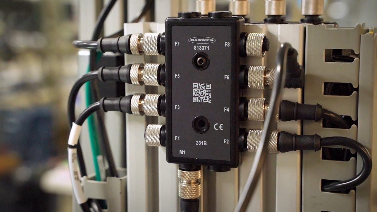
When numerous sensors or actuators need to be connected to a single IO Master, designers can use an IO-Link hub to aggregate sensor and actuator signals and transmit them to an IO-Link master via a single cable. For example, the R90C-4B21-KQ features four input ports and connects to the master using a standard M12 connector (Figure 4). It’s a compact bimodal (PNP or NPN) to IO-Link device converter that connects discrete inputs and sends the value to an IO-Link Master. It features:
- Delay modes that include ON/OFF Delay, ON/OFF/Retriggerable One-shot, ON/OFF, Pulse-stretcher, and Totalizer
- Measurement metrics include Count, Events Per Minute, and Duration
- Discrete mirroring enables the signals (in and out) to be mirrored to any of the four ports
- Discrete I/Os can be independently configured as NPN or PNP
- Rugged over-molded IP68 rated design
 Figure 4: The R90C-4B21-KQ hub can consolidate communications from four devices and connect them with an IO-Link master device. (Image source: Banner Engineering)
IO-Link signal converters
Various types of converters are available for IO-Link networks to connect sensors and other devices that may use a range of signal types, such as discrete PNP or NPN signals, analog 0 to 10 VDC signals, and current transducers. Examples of IO-Link signal converters include:
- R45C-K-IIQ IO-Link to analog current in or out converter (Figure 5)
- R45C-K-UUQ converter for analog voltage in or out
- R45C-K-IQ converter for analog current out
- R45C-K-UQ converter for analog voltage out
 Figure 5: The R45C-K-IIQ IO-Link converter can connect a master device with local devices using analog inputs and outputs. (Image source: Banner Engineering)
IO-Link inline converters are also available that are about the size of a single AA battery. These converters can handle various signal types and convert them to IO-Link, Modbus, or other protocols. For example, the S15C-I-KQ is an analog current to IO-Link converter that connects to a 4 to 20 mA current source and outputs the value to an IO-Link master. The small size of these converters simplifies the addition of legacy sensors into networks with standard protocols for process or environmental monitoring. Their IP68 ratings enable them to be broadly deployed in industrial settings.
Conclusion
IO-Link provides the connectivity needed to gather the data necessary to optimize the performance of Industry 4.0 factories by connecting legacy and other edge devices with the main Ethernet IP, Modbus TCP/IP, or PROFINET network. It supports high levels of data availability, extended diagnostics, remote configuration, and simplified device replacement, speeding process and line changes using connectivity that is standardized in IEC 61131-9 with simple unshielded 3 or 5 wire standard cables defined in IEC 60974-5-2.
Recommended Reading
Disclaimer: The opinions, beliefs, and viewpoints expressed by the various authors and/or forum participants on this website do not necessarily reflect the opinions, beliefs, and viewpoints of DigiKey or official policies of DigiKey.