Use a Comprehensive PLC Reference Design to Accelerate Development of Industrial IoT Applications
Contributed By DigiKey's North American Editors
2019-02-07
Industrial Internet of Things (IIoT) applications promise to enhance the efficiency of complex industrial systems. Enabling these IIoT applications are next generation microcontroller-based programmable logic controllers (PLCs) that challenge developers to support the broad range of industrial interfaces required in these systems, while making the devices compact enough to fit within the factory equipment.
These challenges form a significant roadblock toward the ultimate objective of creating more sophisticated IIoT applications. However, a modular approach to custom PLC IO may be the solution developers need.
This article will discuss the challenges associated with sophisticated IO design for the IIoT. It will then introduce a modular system solution, in this case from Maxim Integrated, before showing how to use it as either a ready-made solution, or as a reference design for a modern, custom, IIoT application.
The evolving role of PLCs in the IIoT
In their role as intermediaries in factory automation systems, PLCs have for years provided the multiple interfaces required to connect sensors, actuators, and other equipment to host systems. In serving IIoT applications, PLC systems need to support significantly greater numbers of end devices and local processing capability, while remaining small enough to fit onto individual pieces of machinery or sit unobtrusively in work cells or sub assembly lines. This can bog down developers in the design details associated with the many interfaces required in an industrial environment.
In many cases this is an inefficient use of developer time that may be better spent on providing high level solutions for smart factories, adaptive manufacturing, predictive maintenance, and other emerging capabilities built on artificial intelligence methods. Using a flexible, modular interface approach to sensors and actuators development time can be shortened, but that interface solution must still be robust enough to tolerate harsh industrial environments.
Industrial interfaces
A typical industrial environment requires a broad mix of interfaces for both digital and analog signals between peripheral devices and host systems. Among these, the IO-Link industry standard has emerged as an effective approach for connecting compatible end devices as well as legacy sensors and actuators.
In a standard point-to-point IO-Link connection, developers use an IO-Link master in a PLC to connect to an IO-Link transceiver across low-cost 3 or 4 wire unshielded cable terminated with standard M12 connectors. Through its electrical interface and functional protocol, IO-Link ensures reliable communications even in harsh, electrically noisy industrial environments. IO-Link master devices such as the Maxim Integrated MAX14819 hide the complexity of implementation of the IO-Link electrical interface and protocols. For the electrical interface, the MAX14819 integrates circuitry needed to generate regulated L+ and L- power sources and C/Q data signals required in the IO-Link standard. For the communications protocols, the device integrates the IO-Link framers, UARTs, and FIFOs underlying the IO-Link messaging method (see, “Use IO-Link Transceivers to Cut Power, Boost Performance, and Simplify Development”).
To connect a sensor or actuator to an IO-Link master in a PLC, developers can readily find compatible IO-Link devices or easily build their own using the Maxim MAX14827A transceiver (Figure 1).

Figure 1: Developers can rapidly implement IO-Link point-to-point communications links by pairing a Maxim Integrated MAX14827A IO-Link transceiver in a peripheral sensor with a Maxim MAX14819 IO-Link master in a PLC or other host system. (Image source: Maxim Integrated)
Although IO-Link has become well-established in newer industrial environments, other standard interfaces continue to find application in both legacy and more recent environments. Among these, RS-485 remains one of the most widely used serial interface standards. Designed as a more robust alternative to earlier serial interfaces such as RS-232 or RS-422, RS-485 is a standard electrical interface used for bidirectional communications across a 24 AWG twisted-pair. Its common-mode performance characteristics have earned it a central role in meeting requirements for reliable operation across extended cable lengths, even in noisy environments. Accordingly, it provides the foundation of many factory networks, serving as the physical layer (PHY) in Profibus and Fieldbus, for example.
As with IO-Link, engineers can readily find integrated devices designed to simplify implementation of RS-485 communications. Built specifically for industrial applications, the Maxim Integrated MAXM22511 RS-485 transceiver not only simplifies implementation of this interface, but also protects its integrity in harsh environments. Using the device, developers can implement a galvanically isolated RS-485 interface with no additional components by simply connecting the cable side of the MAXM22511 to a twisted pair, and the UART side of the MAXM22511 to a microcontroller or other digital device (Figure 2). Integrated within the device, high voltage capacitors isolate data channels, and a transformer built into the device’s DC-DC regulator provide an isolated power source to the cable side through an on-chip low-dropout (LDO) regulator.

Figure 2: The Maxim Integrated MAXM22511 transceiver simplifies implementation of industrial RS-485 interfaces while providing built-in isolation protection from electrical events on the cable side. (Image source: Maxim Integrated)
In practice, a typical industrial automation system will likely require support for interfaces beyond IO-Link and RS-485 interfaces. On the input side, these systems typically need to support digital input devices that comply with IEC 61131-2 and all three of its input types: Type 1 for older 3-wire sensors with mechanical switching contacts, Type 2 for earlier 2-wire sensors with semiconductor interfaces, and Type 3 for more recent 2 or 3-wire low-power sensors.
Here, developers can turn to the Maxim MAX22192 which provides eight IEC 61131-2-compliant input channels that can each be configured to Type 1, 2, or 3 inputs with the simple addition of current setting resistors.
On the output side, many of these systems depend on digitally controlled drivers able to support high-speed switching needed for precise control of actuators or other equipment. Here, engineers can use a device such as the Maxim Integrated MAX14912, which provides eight channels that can be configured as high-side switches or drivers.
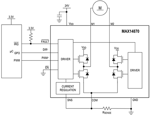
For more specialized output requirements such as direct control of DC motors, developers can turn to the Maxim MAX14870, which provides a fully integrated motor control solution designed to reduce parts count and design complexity. In response to a pulse-width modulation (PWM) signal and direction (DIR) control signal, the device’s integrated drivers directly drive DC brushed motors and relays at voltages up to 36 volts with minimal additional components (Figure 3). Designers can combine the MAX14870’s output capabilities with the Maxim MAX14890E encoder receiver to implement precision motion control subsystems.

Figure 3: The Maxim Integrated MAX14870 integrates drivers and switches allowing developers to implement PWM controlled motor subsystems with few additional components. (Image source: Maxim Integrated)
Next generation PLC design
The availability of a broad array of specialized ICs has alleviated many of the low-level design challenges associated with implementing the various interfaces required for industrial systems. Even so, the sheer number of required interface devices, each with their own design requirements, still leaves engineers to deal with the challenge of combining multiple interface devices with a microcontroller in the smallest possible design footprint. The Maxim Integrated MAXREFDES212 Go-IO PLC system eliminates even this hurdle for developers looking to build the foundation for sophisticated IIoT applications.
The Maxim Integrated MAXREFDES212 Go-IO PLC system is a modular system comprising several small boards each designed to meet a range of requirements for next generation PLCs. Designers plug an application processor board (MAXREFDES211), an IO-Link factory automation board (MAXREFDES200), and a motion control board (MAXREFDES201) into a base board (MAXREFDES215) that provides IO terminal block and separate IO-Link-compatible M12 connectors (Figure 4). (Note that Maxim provides the indicated MAXREFDESxxx designations for the four boards, but those boards are available only as part of the MAXREFDES212 Go-IO PLC system.) Plugged together, the boards included in the Go-IO system provide a compact microcontroller-based PLC measuring less than three square inches, while offering over 20 IOs supporting a full range of interfaces including IO-Link, RS-485, IEC 61131-2-compliant digital input, digital output, and motor control. Developers can immediately use the Go-IO PLC to supplement existing industrial systems or use it as a reference design for custom PLCs.

Figure 4: The Maxim Integrated GO-IO PLC modular design lets developers configure a PLC by plugging in separate boards including an Arm microcontroller-based application processor board (MAXREFDES211), a factory automation board (MAXREFDES200), and a motion control board (MAXREFDES201) into a base board (MAXREFDES215). (Image source: Maxim Integrated)
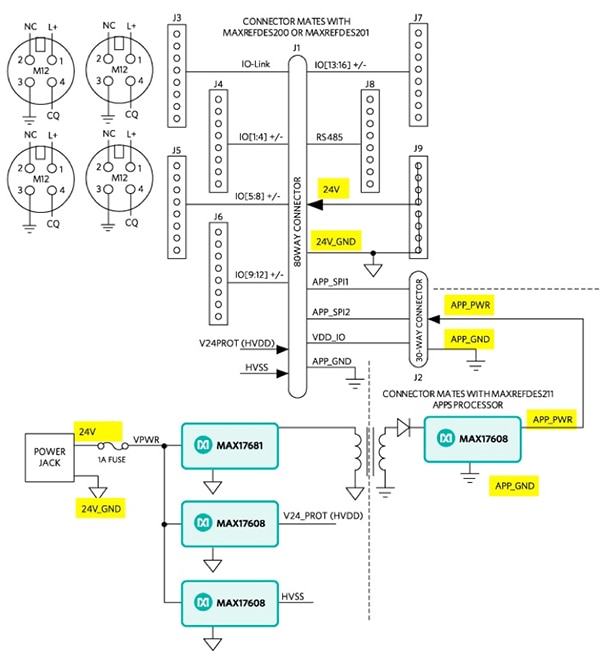
Besides its role as the physical framework for the PLC, the carrier board provides the add-on boards with a regulated voltage supplied from a standard 24 volt wall adaptor, or from a separate high current source attached to screw terminals on the carrier board. Here, the board design combines a Maxim MAX17681 DC-DC converter, inductor, and MAX17608 current protection IC to provide isolated power to the other boards (Figure 5). Additional MAX17608 devices provide protection to additional 24 volt supplies available for use on the individual boards.

Figure 5: The Maxim Go-IO carrier board provides connectors and power for other boards included in this modular approach to PLC design. (Image source: Maxim Integrated)
Designed to be plugged into the base of the carrier board, the application processor board includes a Maxim MAX32630 microcontroller and support features for development and execution of code for the assembled PLC (Figure 6). Based on an Arm® Cortex®-M4 with FPU CPU, the MAX32630 provides the combination of low power, security, and processor performance required in emerging IIoT PLCs. Drawing power from the carrier board, the application processor board uses a MAX17502 DC-DC converter to step down the 24 volt source to 3.3 volts to supply two MAX1806 linear regulators, which provide the 1.8 volt and 1.2 volt supplies required by the MAX32630.

Figure 6: The Maxim Go-IO application processor board hosts the Maxim MAX32630 microcontroller that orchestrates the function of add-on boards, communicating through a shared SPI bus through an 80-way connector used to interconnect the various boards used in this modular system. (Image source: Maxim Integrated)
Along with USB connectors for interfacing with a development system, the board supports 1-Wire, I2C, UART, and SPI connections. In fact, the application processor board provides multiple SPI buses for use throughout the modular Go-IO system. Two SPI buses, APP_SP1 and APP_SP2, connect to the 80-way connector for use by the other plug-in boards. As described below, APP_SP2 plays a particularly important role in system protection.
The final two SPI buses are unused as of this writing: The SD_SPI bus is reserved for connecting an SD card, and WIFI_SPI bus is reserved for a Wi-Fi module. Although currently unsupported, the design hardware specifications include a Microchip Technology ATWINC1510-MR210PB1952 Wi-Fi module, which provides a complete Wi-Fi subsystem including power amplifier (PA), low-noise amplifier (LNA), switch, and a trace antenna.
Although the application processor board works solely within a controlled digital domain, industrial interfaces are always susceptible to sudden high voltages from cable shorts or static discharge. Whatever the source, these can degrade or destroy digital electronics designed to operate within narrow voltage rails. As mentioned earlier, interface devices such as the Maxim Integrated MAXM22511 RS-485 transceiver IC feature built-in isolation designed to protect its digital circuitry from cable side effects. At the board level, however, engineers need to build isolation into the overall design. The Go-IO PLC system reference design demonstrates a system-level approach to isolation.
Designed to protect connections to the APP_SPI2 bus, the MAXREFDES212 kit and reference design uses a common isolation approach for both of the remaining two add-on boards, the factory automation and motion control board. In this approach, multiple digital isolation devices protect the APP_SPI2 SPI bus and other signal lines carried on the 80-way connector. This connector links devices on the add-on boards to the MAX32630 microcontroller on the application processor board.
Here, the Go-IO design takes advantage of the isolated SPI interface built into the MAX22192 to provide a protected board-side SPI bus for other add-on board devices, including a Maxim MAX3108 UART that is built into each of the add-on boards. The Go-IO design also incorporates a Maxim MAX14483 IC that provides six isolated channels optimized for SPI transactions. Finally, the design uses several Maxim MAX14130 four-channel digital isolators configured to provide protection for additional SPI connections and specific signal lines.
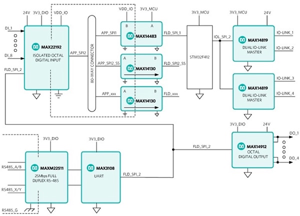
Although the configurations of the MAX14483 and MAX14130 digital isolators are slightly different on the two add-on boards, both boards share the general architecture described above and found in the design of the factory automation board (Figure 7). Along with the similar approach to isolation, both boards have access to the IEC 61131-2-compliant inputs provided by the Maxim MAX22192, as well as the protected RS-485 interface provided through the MAX3108 and MAXM22511.

Figure 7: The Maxim Go-IO factory automation board provides isolated connections between the microcontroller and specialized interface devices, providing developers with support for multiple industrial interfaces including digital input, digital output, RS-485, and IO-Link. (Image source: Maxim Integrated)
The primary difference between the two add-on boards lies in the configuration of devices used to support the factory automation interfaces supported by one board and the motion control features supported by the other. In the factory automation board (MAXREFDES200), the protected SPI buses and signal lines connect to high-speed output drivers and to an IO-Link subsystem. Here, the board design provides digital output control using the previously mentioned Maxim MAX14912 high-speed switch/driver. For the IO-Link subsystem, the board design combines a pair of Maxim MAX14819 IO-Link master transceivers with an STMicroelectronics STM32F412 microcontroller that executes its preloaded IO-Link protocol stack.
For regulated power, each board incorporates a pair of Maxim MAXM15462 DC-DC converters to step the 24 volt supply from the carrier board down to the supply levels required on each board as 3V3_DIO, 3V3_MCU, and 5V0_DIO. In addition, the MAX22192’s integrated LDO converts the 24 volt supply to a 3.3 V VDD_IO supply used by the MAX14130 digital isolator IC in its protected domain.
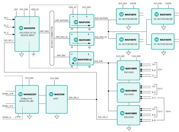
For the motion control board (MAXREFDES201), the design combines digital isolation devices with a set of MAX14870 motor drivers and MA14890 encoders (Figure 8). As noted earlier, the combination of the MAX14870 and MA14890 provides developers with the key capabilities required to implement precision control systems built with motors, relays, and other devices.
Figure 8: Incorporating a protection scheme similar to that used in the factory automation board, the Go-IO motion control board provides developers with driver output and encoder inputs needed to implement advanced control features for motor, relay, and other industrial subsystems. (Image source: Maxim Integrated)
To help engineers accelerate software development for the Go-IO PLC system, Maxim provides a basic software package containing drivers and basic test routines. Although the underlying framework is preloaded as firmware in the Maxim MAX32630 microcontroller, developers can study sample software that demonstrates basic design patterns for interacting with individual devices through the system’s application programming interface (Listing 1). With its focus on the industrial IO interface, the GO-IO PLC system hardware reference design and accompanying software provide the critical foundation required to implement advanced industrial automation systems.
Copy
* ************************************************************************* */
int TEST_MAX22192_run_tests(void){
    int error;
    di_channel_t di_ch;

    TEST_print_line(0, 0, 0);
    TEST_print_header("MAX22192 Tests", 0);
    TEST_print_header("HW", 0);

    //Read input for channel 1
    di_ch = DI1;
    error = MAX22192_read_input(di_ch);
                printf("Test- MAX22192_read_input(%d): %d", di_ch, error);
    TEST_print_pass(error == 1, 1);
    . . .

/* ************************************************************************* */
int TEST_MAX14912_run_tests(void){
    int error;
    int counter;
    do_channel_t do_ch;
    do_mode_t do_mode;
    uint8_t do_value;

    TEST_print_line(0, 0, 0);
    TEST_print_header("MAX14912 Tests", 0);
    TEST_print_header("HW", 0);

    //Write mode for channel 1
    do_ch = DO1;
    do_mode = DO_MODE_HS;
    error = MAX14912_write_mode(do_ch, do_mode);
                printf("Test- MAX14912_write_mode(%d, %d): %d", do_ch, do_mode, error);
    TEST_print_pass(error == 0, 0);
    . . .
Listing 1: The Maxim Integrated sample software distribution includes test code that demonstrates basic design patterns for peripheral operations including reading (MAX22192_read_input()) from individual channels in the Maxim Integrated MAX22192 digital input IC and writing (MAX14912_write_mode()) to individual channels in the Maxim Integrated MAX14912 digital input IC. (Code source: Maxim Integrated)
Conclusion
Sophisticated applications of dynamic manufacturing, predictive maintenance, and other advanced artificial intelligence methods rely on reliable connections to sensors, actuators, and other industrial equipment. The Maxim Integrated Go-IO PLC modular system and reference design provides a ready-made platform for existing environments and an extensible foundation for addressing emerging requirements. By building on the Go-IO PLC platform, developers can rapidly deploy a compact PLC solution to implement advanced manufacturing systems.

Disclaimer: The opinions, beliefs, and viewpoints expressed by the various authors and/or forum participants on this website do not necessarily reflect the opinions, beliefs, and viewpoints of DigiKey or official policies of DigiKey.


