Use a Smart Sensor’s Built-In Machine Learning Core to Optimize “Always-On” Motion Tracking
Contributed By DigiKey's North American Editors
2019-06-11
Growing consumer demand for “always-on” motion tracking features in fitness trackers and other personal mobile devices has in the past meant designers needed to choose between those features and battery life. Attempts to reduce power consumption inevitably meant sacrificing tracking capability or resolution, thereby compromising the user experience.
The emergence of low-power sensors with built-in motion detection capabilities helps developers eliminate this compromise in their designs.
This article describes and shows how to use a smart motion sensor from STMicroelectronics that integrates sophisticated motion processing capabilities to offer a more effective solution for low-power, always-on motion tracking.
Classic power management practices
In a typical low-power mobile system design, the power consumed by the host microcontroller during its normal active mode accounts for the dominant share of overall system power consumption. As a result, developers look for every opportunity to keep the microcontroller operating in a low-power sleep mode, waking the processor only long enough to handle tasks such as sensor data processing or communication.
For many years, developers have been able to achieve this objective using sensors capable of collecting data independently of the host processor. For applications with modest requirements for sensor output data rate, the sensor could fill its on-chip buffers with a series of measurements, even performing direct memory access (DMA) transactions to transfer the data to system memory before issuing an interrupt to wake the processor to complete its processing tasks. Because the sensor’s integrated signal chain could perform signal conditioning, conversion, and filtering, the processor could immediately begin to work on preprocessed data, looking for events of significance to the application.
With the integration of threshold detection features in these sensors, developers could further extend the time the processor remained in low-power mode. Rather than require the processor to identify significant events, the sensor could issue a wake-up signal only when it measured an event that exceeded the threshold values programmed into it by the developer. For example, a designer could program this type of advanced temperature sensor to issue a wake-up signal only when the measured temperature exceeded a specified maximum threshold or fell below a specified minimum threshold.
Although effective for simpler requirements, this approach for reducing power consumption can be markedly less effective for detecting more complex events. Combined with the requirement for always-on sensing, detection of these complex events means a higher active duty cycle for the processor, quickly draining the relatively low-capacity rechargeable batteries typically used in personal wearable devices. So, it follows that the traditional use of the host microcontroller to perform detection becomes unsustainable in the face of rising user demand for both always-on detection and longer battery life.
If instead the sensor can execute more complex detection algorithms, developers can continue current best practices for reducing system power consumption through low-power operating modes and processor sleep states. At the same time, this more intelligent sensor needs to provide developers with a high degree of flexibility. Simply hardwiring a few specific algorithms into sensors will fall short of demand for new and better product features. The STMicroelectronics LSM6DSOX iNEMO (LSM6DSOXTR) inertial sensor achieves this flexibility with a combination of signal processing features and flexible computational capabilities built into the device.
Sensor architecture
The LSM6DSOX iNEMO is a system-in-package (SiP) that combines microelectromechanical systems (MEMS) sensors, dedicated signal chains, filters, and specialized computational engines in a land grid array (LGA) package measuring only 2.5 x 3.0 x 0.83 millimeters (mm). Along with its internal three-axis accelerometer and a three-axis digital gyroscope MEMS sensors, the device can be configured as a sensor hub with the ability to separately orchestrate the operation of up to four external sensors through dedicated hub registers.
Based on the same architecture as the earlier STMicroelectronics LSM6DSO, the LSM6DSOX offers all the capabilities and features of that earlier device (see, “IMUs: Let Your Host Sleep with On-Board Machine Learning”). With the LSM6DSOX, however, STMicroelectronics complements the finite-state machine (FSM) offered in the earlier device with a machine learning (ML) core for classification of data sets through up to eight decision trees. Even without engaging the FSM and ML core capabilities, developers can implement advanced motion detection capabilities thanks to the advanced signal chains used to preprocess data from the MEMS sensors.
As with many advanced sensors, the LSM6DSOX architecture features multi-stage signal chains that combine an analog-to-digital converter (ADC) with multiple filtering stages. The gyroscope signal chain complements the ADC stage with a series of selectable digital filters including a high-pass filter (HPF), a low-pass filter (LPF1), and a second low-pass filter (LPF2) that operate in the device’s high-performance mode but are bypassed in normal or low-power modes (Figure 1).
 Figure 1: As with the earlier STMicroelectronics LSM6DSO, the STMicroelectronics LSM6DSOX follows each sensor with a specialized, dedicated signal chain with multiple filter stages as shown here for the gyroscope sensor. (Image source: STMicroelectronics)
Because the accelerometer is required for many of its integrated capabilities, the accelerometer signal chain is significantly enhanced in this architecture. Its initial stages provide the basic signal conditioning and conversion capabilities found in most advanced sensors. For example, an analog anti-aliasing low-pass filter provides basic signal conditioning, a 16-bit ADC digitizes the conditioned signals, and the digitized results are passed through a digital low-pass filter. What sets the device apart is the sophisticated composite filter block that follows this initial conversion stage (Figure 2).
 Figure 2: Used in both the earlier STMicroelectronics LSM6DSO and now the STMicroelectronics LSM6DSOX motion sensor, an extensive accelerometer signal chain supports host-independent detection of several complex movements including free fall, multidimensional orientation, and single/double (S/D) tap. (Image source: STMicroelectronics)
Using a combination of processing blocks and filters, the accelerometer’s composite filter section can autonomously detect a wide variety of complex events that until now required the processor to wake and run specialized event-detection code. Instead, developers can now program filter parameters to automatically detect and issue interrupts for a wide range of complex motion events including single or double tap, free fall, activity/inactivity, orientation with six degrees (6D) of freedom, or 4D orientation typically used to detect movement of the device. For example, from portrait to landscape mode.
The composite filter’s advanced detectors combine the results from the processing blocks and filters to perform their detection. For example, single tap detection uses the built-in slope filter, which continuously generates the slope at the current accelerometer sample, acc(tn), as:
slope(tn) = [ acc(tn) - acc(tn-1) ] / 2 (Equation 1)
For a single tap event, the slope rises above some threshold and falls quickly compared to a broader shock event (Figure 3). Using tap threshold and shock window duration values set by the developer, the device can automatically detect the single tap event and issue an interrupt to the host microcontroller.
Double tap detection builds upon this approach, adding an additional parameter to specify the required wait time between the two single tap events.
 Figure 3: The LSM6DSO and LSM6DSOX motion sensors provide host independent detection of single tap events using a built-in slope function that exhibits a more rapid return to baseline levels for a single tap (a) compared to the signature of a broad shock event (b). (Image source: STMicroelectronics)
The device’s ability to generate derived data, such as slope, plays a central role in the more advanced capabilities available with its integrated FSM and machine learning (ML) core. Since the FSM feature has been discussed in the previously referenced article, the remainder of this article will focus on the LSM6DSOX’s ML core and its use in detecting much more complex motion events, including motion sequences and even complex movement activities such as specific exercises.
Decision trees
The LSM6DSOX’s ML core provides sensor-based processing to a level well beyond the familiar parameterized threshold settings used in many advanced smart sensors. Using the ML core, developers can implement complex detection algorithms in the device, allowing always-on detection of complex motion events without the need to wake the microcontroller. Here, the ML core uses decision trees to identify an event based on patterns of input data.
Used for years in decision support systems, decision trees decompose complex decisions down into a series of selections based on testing the input data, or attributes, against predefined conditions. Starting at the initial node, or root, an attribute’s value is tested and the decision to continue to a particular child node is determined by the results (Figure 4).
 Figure 4: A decision tree generates a result using a sequence of nodes that each test an input value for a particular attribute against a condition such as a particular threshold level, continuing on to different child nodes depending upon the results of the test. (Image source: STMicroelectronics)
For example, at each update cycle, the decision tree would be invoked to work through its nodes to determine if the data available – with that update – represented no movement, forward movement, or some other movement as follows:
- test the magnitude of an accelerometer measurement
- 1.1. terminate if the value is below some predetermined value (the condition)
- 1.2. otherwise, branch to a child node to test gyroscope measurements taken in the same time window
- 1.2.1. terminate if gyroscope measurements are below some predetermined value or
- 1.2.2. continue to a deeper child node to test other attributes measured in the same time window or test the same attribute against another condition.
This process repeats until the test reaches a terminal node, which in this context corresponds to a particular complex motion event, or class. In this simple example:
- terminal node 1.1 might indicate that the data, or feature set, should be classified as “no movement”
- terminal node 1.2.1 might indicate that the feature set should be classified as “forward movement”
- terminal nodes below node 1.2.2 might be indicative of a moving turn or more complex change in orientation
Of course, real-world problem sets that require the use of decision trees are much more complex, involving large feature sets comprising many different attributes and conditions. In fact, the LSM6DSOX provides developers with a rich set of possible features starting with sensor data from the accelerometer, gyroscope, and any external sensors attached in sensor hub connection mode (Figure 5).
 Figure 5: Unique to the STMicroelectronics LSM6DSOX, a built-in ML core uses primary sensor data, filtered data, and derived parameters, such as mean and variance, as inputs to one of eight decision trees supported by the device. (Image source: STMicroelectronics)
From this primary sensor data, the device generates a large number of features calculated from primary data within a sliding time window including:
- norm V = Ö( x2 + y2 + z2) and V2
- mean
- variance
- energy
- peak to peak
- zero crossing
- positive zero crossing
- negative zero crossing
- peak detector
- positive peak detector
- negative peak detector
- minimum
- maximum
For certain features such as the zero-crossing detectors and peak detectors, the developer also specifies a threshold value for shifting the zero-crossing axis or peak threshold, respectively.
Supervised learning workflow
Using these features to implement a decision tree with the LSM6DSOX’s ML core follows a typical supervised learning workflow common to most machine learning model development efforts. In general, this workflow starts with identification of the activities of interest and collection of data samples associated with those activities.
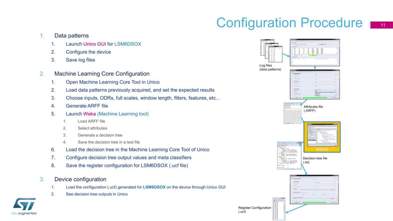
In this case, developers simply use the LSM6DSOX to collect data while performing the particular set of motion activities that the final application will need to detect. For this phase of development, developers can create a data acquisition platform using boards and software from STMicroelectronics. For the hardware platform, developers simply plug the STEVAL-MKI197V1 LSM6DSOX adaptor board into the STEVAL-MKI109V3 evaluation motherboard. For software, developers can use STMicroelectronics’s free Unico software tool, available for Windows, Mac OSX, and Linux.
Designed to work with the STEVAL-MKI109V3 motherboard, Unico provides a simple method to collect data generated by the LSM6DSOX. For data collection, developers use the motherboard and Unico together. Here, the developer or an assistant holds onto the motherboard while repetitively performing one of the specific movement activities of interest, using Unico to collect LSM6DSOX motion data.
The data collected from the LSM6DSOX during multiple repetitions of a single activity provides the training set for the corresponding class (such as “forward movement” in our earlier example). Because data collected during that movement all corresponds to that same class, this active approach to data collection eliminates the need for a separate data labeling phase that can sometimes delay supervised learning workflows.
After collecting motion data for each movement event class of interest, developers use Unico to review the data and the class label. Beyond its use for data review, Unico lets developers configure multiple aspects of the desired decision tree, define filters, set time window duration, and select the specific features to use in building the decision tree.
In practice, developers typically limit the features used to detect a particular set of activities to the smallest possible number as determined by experience and experimentation. Given even a minimal feature set, the task of implementing a decision tree efficiently depends critically on determining which of those features, or attributes, to test at each node of the decision tree. Choosing the “best” attribute to test at each node is important for minimizing the size of the decision tree, which is particularly important for a resource limited device like a sensor.
Note for the reader: By now you may be wondering about the use of feature vs attribute. The difficulty is we talk about “features” for ML models, but those are called “attributes” in decision tree speak. We’ve tried to stick with one or the other in a section, but here we switch from “feature” to “attribute” for the following decision tree discussion. You’ll no doubt note other places the two are used interchangeably, but here and later in the “arff” section, it’s “attribute.”
Although simple in concept, the selection of the best attribute to use at each decision node can be non-intuitive for decision trees with a large number of attributes, each represented by a wide range of data values. The favored approach for finding the best attribute to test at each node requires calculating each attribute’s Shannon entropy at that node using Equation 2:
entropy(p1,p2,...,pn) = - p1log2(p1) - p2log2(p2)... - pnlog2(pn) (Equation 2)
The probability pn represents each of the n possible classes associated with that attribute.
The result is the information content, presented in bits ranging in value from 0 to 1, rather than just 0 or 1, in the more familiar definition of bits.
The information “gain” of each attribute then becomes the difference between this information value and the baseline information value calculated for the attribute based on a probability of a correct decision that would occur without use of the decision node. Although a detailed look at this calculation is beyond the scope of this article, an intuitive interpretation involves comparing which approach will more likely provide the desired outcome more efficiently: A result based on a brute force bottom-up slice through the data set based on values of that attribute (the “baseline”), or a result based on a top-down selection based on specific ranges of values for that attribute. Top-down selection uses a “divide and conquer” approach that will typically reduce the number of possible outcomes more quickly than the bottom-up approach.
Rapid deployment
Fortunately, developers seldom need to concern themselves with the details of information gain and attribute selection optimization. Instead, they can take advantage of freely available third-party machine learning tools such as Weka that automatically handle the calculations needed to generate optimal decision trees.
In fact, Unico and Weka closely work together to provide a workflow for rapid implementation of decision trees. Typically, the critical steps in a specific decision tree development workflow lie in the data collection steps mentioned earlier, specifically, using the LSM6DSOX to collect representative data sets for each activity class of interest; and using Unico to refine those data sets and define the decision tree configuration. Once completed, these two tools combine to speed the final stages of the process.
After refining the data and decision tree configuration in Unico, developers use the tool to convert the selected feature set into a standard format called the attribute-relation file format (arff). An arff file includes a header section which lists the selected attributes (features) and possible classes, and a data section which lists each set of collected data and the associated class (Listing 1). In this example, only a very few features are used, and only a small set of data instances are used to identify a limited set of classes including bicep curls, lateral raises, and squats).
") Listing 1: The standard attribute-relation file format (arff) file includes a header section which defines attributes and classes, and a data section which contains data instances for each attribute and associated class. (Data source: STMicroelectronics)
Listing 1: The standard attribute-relation file format (arff) file includes a header section which defines attributes and classes, and a data section which contains data instances for each attribute and associated class. (Data source: STMicroelectronics)
Using Weka, developers load the arff file in the “preprocess” window and view a graphical summary of the full feature set (Figure 6).
 Figure 6: After using the STMicroelectronics Unico tool to generate an arff file for their data set, developers can use Weka, a third-party machine learning tool, to view the complete data set, shown here for the arff data in Listing 1. (Image source: DigiKey)
To build the decision tree, developers switch to the Weka “classify” window, choose the Weka J48 classifier (Weka’s decision tree classifier), and click start. In its output window, the classifier lists a summary of the input data and provides the decision tree in both graphical (Figure 7) and text format (Figure 8).
 Figure 7: To create a decision tree, developers simply load an arff file, select the Weka J48 decision tree classifier, and generate the final tree. The built-in Weka visualization tool is used to view the result with attributes and conditions listed for each node – in this case using the arff data in Listing 1. (Image source: DigiKey)
 Figure 8: Along with a visual display of the decision tree, Weka generates the actual J48 decision tree specification – in this case using the arff data in Listing 1 to generate the J48 specification in Listing 2. (Image source: DigiKey)
In this example, the generated J48 decision tree specification requires only a few lines (Listing 2).
 Listing 2: Weka generates a J48 decision tree specification such as this one for the arff data in Listing 1. Developers load this specification into the STMicroelectronics Unico tool to generate a configuration file and load it into the STMicroelectronics LSM6DSOX sensor. (Data source: STMicroelectronics)
After copying and saving the J48 tree text to a file, developers load that text file into Unico to generate a register configuration file. Finally, developers complete the workflow by using the Unico load/save tab to load that configuration file into the LSM6DSOX. At this point, the developer can perform the support movements while holding the STEVAL-MKI109V3 motherboard as described earlier, using Unico to read the decision tree classification result from the LSM6DSOX output register for the configured decision tree.
In a custom design, developers could use a change in a decision tree output register to signal the microcontroller to wake and execute code to signal the user, increment an exercise counter, or other suitable higher level operation required by an application.
Although this example is simple in the extreme, the LSM6DSOX ML core can support classification of dramatically more complex motion events using more of the different features mentioned earlier. For example, STMicroelectronics describes a more advanced version of this simple application, using many more features to classify gym activity into a wider range of exercises including bicep curls, jumping jacks, lateral raises, push-ups, and squats.
Along with the mean and peak-to-peak features used in the simple example, the complex example adds variance, min, max, and zero-crossing features calculated for a two-second time window. Running in the LSM6DSOX ML core, this more sophisticated application results in current consumption of about 569 μA (@ 1.8 V) of which only about 13 μA is due to current consumption by the ML core itself. At this level of power consumption, developers could confidently implement always-on motion detection with only modest impact on a battery’s state of charge.
Machine learning caveat
Real-world applications of machine learning depend on supervised learning workflows that inevitably incorporate some form of bias in the final machine learning model, whether that model is a very complex convolutional neural network or relatively simple decision tree. Motion-based data, in particular, is so dependent on physical morphology and kinesiology that the data collected from one individual performing an activity may differ markedly from that of another.
As a result, developers using ML-based activity detection face a continuing challenge of finding the balance between data specificity and generality. Too much specificity typically limits generality, while too much generality typically erodes the accurate detection of different individuals’ unique variations of the same movement. Although these problems are hardly unique to this specific implementation, the challenges of finding this balance in personalized motion detection devices might suggest the need for decision trees that can be updated with user-specific data. With careful attention to these broad machine learning data science requirements, however, developers can already use the LSM6DSOX and existing workflow to incorporate sophisticated, always-on motion detection in power-constrained designs.
Conclusion
Demand for both always-on motion tracking and extended battery life has presented a seemingly insurmountable conflict to developers of fitness devices and other small wearables. Although many advanced sensors can provide some degree of motion detection independent of the processor, the desire to support always-on detection of more complex movements precludes this approach in emerging applications.
Using the machine learning capabilities in the STMicroelectronics LSM6DSOX motion sensor, however, developers can resolve the conflict between always-on tracking and extended battery life to create more advanced, activity aware fitness bands and other wearable devices.
Disclaimer: The opinions, beliefs, and viewpoints expressed by the various authors and/or forum participants on this website do not necessarily reflect the opinions, beliefs, and viewpoints of DigiKey or official policies of DigiKey.