UDOO Neo Ideal for IIoT Designs Where Extensive I/O Sensors and Powerful Compute Resources are Key
Contributed By DigiKey's European Editors
2016-06-22
The Internet of Things (IoT) is seen as being responsible for the fast growth of compact headless microcontroller boards designed for a wide variety of edge node devices such as sensors and actuators. With a small amount of I/O, a wireless microcontroller, and consuming very little power, such boards and modules will make up the army of devices feeding data to cloud-based analytics services. For many applications there exists a requirement for more compute resource, operator interface and connectivity options.
Whether performing a gateway function or aggregating data from many sensors, initiating local control or a mixture of functions, there exists a need for a single board computer with more functionality and resources. As manufacturers of industrial equipment grapple with how to build an embedded device that can meet all the likely diverse needs of each piece of equipment, many will opt for a platform approach, which uses a main embedded board and peripheral add-ons as required. Increasingly, for low to medium volumes, there is much merit in selecting one of a number of increasingly popular open source single board computers (SBC) available on the market. Not only does this save immense amounts of NRE costs, wireless regulatory certification, and software bring-up, but also enables the development team to get started very quickly on the application aspects of the design rather than having to evaluate, design and prototype the myriad of devices they might incorporate.
For many engineering teams, one of the notable impacts of the IoT is that there is a fundamental shift in the way new projects are approached. The team might be extremely capable of designing an embedded board from scratch, but delivering a working design within a narrow deadline is the end-goal. For those that perhaps want to fast track their design using an SBC platform prior to creating their own board, access to all the mechanical files, layouts, and BOM are all necessary.
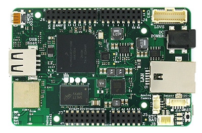
Figure 1: UDOO Neo
An example of an SBC that developers might consider is the UDOO Neo. Available in three different versions, Basic, Extended and Full, they represent a comprehensive and low-cost system, all based around the Freescale i.MX6SoloX applications processor for Android and Linux. For this article, we will be focusing on the Neo Full. This Freescale device embeds on a single chip a powerful single-core ARM® Cortex®-A9 processor running at 1 GHz and an ARM Cortex-M4 I/O real-time co-processor that can run up to 200 MHz. Capable of sharing and using a lot of the hardware implemented features such as GPIO, UART, I2C, etc., they are connected together through a high-speed AXI bus. The developer, through use of editable muxing, can assign the configuration of which peripheral features are used, by which core.
The UDOO Neo Full has 1 GB of Flash and offers a comprehensive range of GPIO, serial interfaces, full Wi-Fi 802.11 b/g/n and BLE connectivity. Equipped with embedded 9-axis motion sensors, a 3-axis accelerometer, magnetometer and gyroscope, LVDS, HDMI, camera, and audio interfaces, this board will suit many industrial designs.
From the operating system perspective, the Cortex-A9 core can run either Android Lollipop or UDOObuntu (14.04 LTS). The Cortex-M4 has access to a full-stack Arduino environment, including full Arduino shield headers, again making it a very flexible platform.
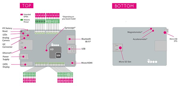
Figure 2: Main features of the UDOO Neo Full board
External pins, shown in red in Figure 2, are by default assigned to the Cortex-A9 in GPIO mode. So these pins can be controlled directly from the file system (Linux, Android). Internal pins, shown in green, are assigned and controlled by the Cortex-M4 with the same dimensions of Arduino UNO pin out.
The board is powered from a single 6 – 15 VDC supply and all GPIO is at 3.3 VDC. A schematic block diagram, Figure 3, highlights the main components and interfaces around the i.MX applications processor.
The Neo suits use as a headless computing platform or, by adding either an LVDS touch panel or HDMI, a platform suitable for user control. If your intended application does not require the motion sensors or as much memory, you can opt for the Basic or Extended versions of the Neo, saving on board cost. For many remote applications a headless configuration is desirable, communication with it being via SSH remote terminal or similar.
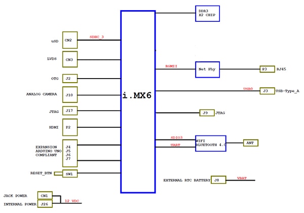
Figure 3: i.MX6 block diagram of UDOO Neo
Getting started with the UDOO Neo couldn’t be any easier. All the necessary information to get the board running together with more comprehensive configuration, code samples, etc. can be found on a Wiki-style site. This site also provides the full mechanical layout files and BOM list should you need them.
As supplied, the board does not have any operating system installed. Whether you opt for Linux or Android you will need to have access to a microSD card having a capacity of 8 GB or more. Download the operating system of your choice from the Neo’s documentation site onto your PC or laptop and unzip it. You will need to then insert your microSD card into a card socket or a USB adapter. Access your computer’s command line, full details here, and follow the instructions to unmount the card, and all partitions, prior to transferring the operating system image. Once finished don’t forget that you need to sync or eject the card to close the image write properly.
Now insert the microSD card into the Neo, attach a mouse and keyboard (USB normally), an HDMI monitor (recommended initially to see that everything is working correctly) and then power up. You should shortly see activity from the green and yellow LEDs on the board, and assuming you opted for Linux, Tux, the Linux Penguin should appear on the screen prior to the UDOO Ubuntu desktop. This familiar desktop gives you access to all the normal features and utilities of Linux. A Neo-configured Arduino IDE is also preloaded in the Linux distribution and is ready for use from the Desktop. The next stage is to connect to the Neo’s web-based control panel. There are a variety of ways to do this, either by pointing the Neo’s browser at its udooneo.local web server, or pointing to the board’s own IP address if you know it. See Figure 4.
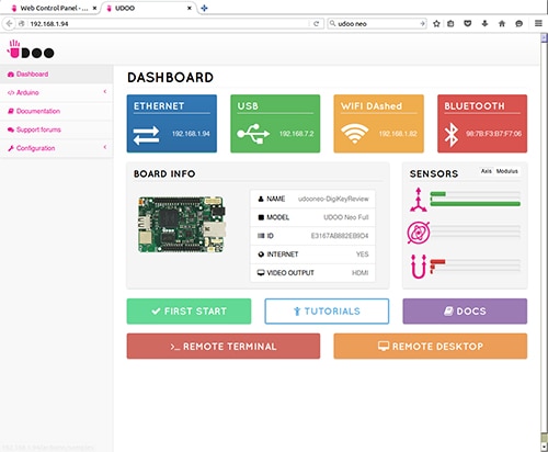
Figure 4: UDOO Neo web control panel
This control panel gives a good insight to what is going on inside the Neo. In addition to presenting information on both wired and wireless connection status, sensors and summary board information, it also provides configuration options to set up and attach to wireless access points, set regional settings and change the display output. Axis and modulus data from the accelerometer, gyroscope and magnetometer are also provided, and you can test their operation by gently moving the board around.
The ability to test sample Arduino sketches and write some simple ones is also provided from the web control panel, see Figure 5. Those familiar with boards such as the Arduino UNO will recognize the simple ‘Blink’ example in the sample application shown in Figure 5 that toggles pin 13. The Neo’s red LED is connected to this pin, so uploading this sketch will cause it to flash. Note that among the programming applications the Ardublocky application is provided that allows the creation of Arduino sketches in a graphical, interconnected logic block manner.

Figure 5: Arduino web IDE and sketch samples
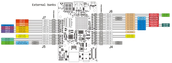
As mentioned earlier, the Neo is equipped with two sets of GPIO. Those accessible from an Arduino sketch, referred to as internal, the inner most set of headers, and those from within Linux, termed external. All are set in an input configuration by default, are configurable as either inputs or outputs and can produce core interrupts if required. Pin muxing allows the MPU to assign more specialized tasks to these external pins.
Figure 6: GPIO accessible from within Linux. Click here to view full-size image.
Control of a GPIO pin can be made from the command line using simple commands such as,
echo out > /gpio/pin19/direction – to set the pin as an output pin or,
echo in > /gpio/pin19/direction – to set the pin as an input pin
A pin designated as an output can be set low, zero volts with echo 0 > /gpio/pin19/value
or to high, +3.3 VDC with echo 1 > /gpio/pin19/value
Input pin values can be read using cat /gpio/pin19/value
The udoo-gpio-export package, preinstalled in UDOObuntu Linux takes care of exporting all GPIO as inputs in addition to creating the links from the /sys/class/gpio directory. More information about advanced requirements like this can be found within the UDOO documentation.
Communication between the Cortex-A9 and the Cortex-M4 cores is made possible through a bi-directional virtualized serial pin that uses shared memory to exchange data. This can be read from within Linux by using /dev/ttyMMC, for example, minicom –D /ttyMCC or within an Arduino sketch using the Serial0 object.
The UDOO Neo Full has three 3-motion sensors on the board. A 14-bit accelerometer and a 16-bit magnetometer are within the same package, a Freescale FXOS8700CQ device. The accelerometer has three dynamically selectable full-scale ranges of +/-2 g, +/- 4 g or +/- 8g.
The 3-axis gyroscope is a Freescale FXAS21002C.
They are attached to the I2C bus, see Figure 7, and can be accessed by either core.
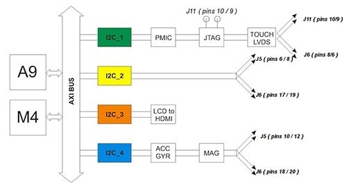
Figure 7: I2C bus showing sensor and device configurations
From the command line they can be enabled with
echo 1 > /sensors/accelerometer/enable or echo 1 > /sensors/gyroscope/enable and one off values can be read with the command such as cat /sensors/magnetometer/data.
Embedded applications will of course be able to read directly from them via the appropriate I2C registers. The accelerometer and magnetometer use address 0x1E and the gyroscope 0x20.
Access to the sensors can also be made through a higher-level language, for example Python. In the early stages of using any new board, you appreciate the open-source and community nature of a board’s design. A good example of this is the Neo.GPIO Python library available on GitHub that provides sensor interface code from within a Python application running on the Cortex-A9. Python is already included in the UDOObuntu distribution so this makes an easy choice to develop with on the Neo. Before use you need to download the .ZIP file from GitHub, and then extract it into the directory you will create your Python application in. Several code examples are included in the .ZIP file too, a simplified version of which is shown in Figure 8.

Figure 8: Python program that reads the gyroscope and displays the data from it
To run the Python code shown in Figure 8 from the command line you must run as root. If you are using the UDOO Neo as indicated above your user account is udooer, so you need to involve the GyroExample.py program in the following manner. See Figure 9.
echo udooer | sudo –S su –c ‘python GyroExample.py’
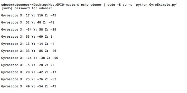
Figure 9: Screen capture of GyroExample.py code running
The UDOO Neo offers a comprehensive and powerful SBC that serves as an ideal development platform for an industrial IoT application. Using Neo you can have your initial application running extremely quickly and bring your product to market in the most time and cost effective way possible.

Disclaimer: The opinions, beliefs, and viewpoints expressed by the various authors and/or forum participants on this website do not necessarily reflect the opinions, beliefs, and viewpoints of DigiKey or official policies of DigiKey.


