The Right Power Supply Regulator Can Minimize DC Rail Noise and Improve Ultrasound Image Quality
Contributed By DigiKey's North American Editors
2023-06-16
Noise is a performance-limiting factor in medical and other ultrasound systems. Of course, the simple term “noise” refers to many distinct types, some of which are inherent in the medical and patient situation, while others are electronic in nature. The dominant patient-induced noise is called “speckle noise” and is largely due to the non-uniformity (non-homogeneity) of the patient’s tissues and organs. Circuit designers can do little about patient-induced noise, but there is much they can do to minimize the various sources and types of due to the electronics.
Among these potential noise sources are DC/DC regulators. To minimize noise, designers can use small and quiet low-dropout (LDO) regulators that continue to improve in efficiency. Even these LDOs can often result in wasted power with associated thermal management issues. The efficient alternative to the LDO is the switching regulator, but these devices have high noise due to their switching nature. This noise needs to be mitigated if designers are to take full advantage of these devices.
Recent innovations in the design of power conversion topologies have reduced that noise, resulting in a shift in the noise-efficiency balance tradeoff. For example, high-power monolithic switching regulators can efficiently power digital ICs with low-noise DC rails, high efficiency, and minimal space requirements.
This article briefly discusses the challenges of ultrasound. It then introduces the tiny Silent Switcher IC families from Analog Devices, and uses the LT8625S as the highlighted example to show how these innovative switching regulators meet the multiple objectives for loads in the single-digit voltage, sub-10 ampere (A) range necessary for high-performance ultrasound imaging. Other Silent Switcher IC examples are provided to show the breadth of the family.
Ultrasound has unique signal-path issues
The operating principle of ultrasonic imaging is simple but developing a high-performance imaging system requires considerable design expertise, many specialized components, and attention to subtle details (Figure 1).
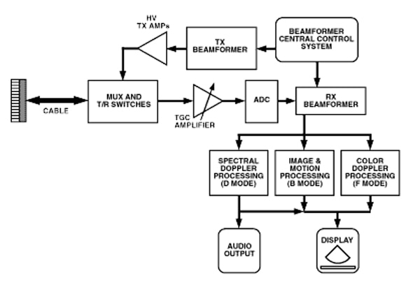 Figure 1: A high-level block diagram of an ultrasound imaging system hints at the complexity of implementing a system based on a simple physics principle. (Image source: Analog Devices)
The imaging system uses an array of piezoelectric transducers that are pulsed to produce an acoustic wavefront. Many new systems have up to 256 such transducer elements, each of which must be controlled independently. The transmitted frequencies range from 2 to 20 megahertz (MHz).
By adjusting the relative timing of the transducers in the array using variable delays, the emitted pulses can be beamformed and aimed at specific locations. Higher frequencies provide good spatial resolution but have relatively poor penetration capability, resulting in degraded image quality. Most systems use around 5 MHz as an optimal compromise.
Once the pulse is emitted, the system switches to receive mode and captures the echoes of the acoustic pulse, which are created whenever the acoustic wave energy hits an impedance barrier, such as at the boundary between different types of tissues or organs. The time delay with which the echoes arrive back with respect to when they are sent provides the imaging information.
Due to unavoidable attenuation of the ultrasound signal as it passes through the tissue twice—once for the forward path and once for the return echo—the received signal level spans a wide dynamic range. It can be as high as one volt down to as low as a few microvolts, which is a range of about 120 decibels (dB).
Note that for a 10 MHz ultrasound signal and a penetration depth of 5 centimeters (cm), the round-trip signal is attenuated by 100 dB. Therefore, to handle an instantaneous dynamic range of about 60 dB at any location, the required dynamic range would be 160 dB (a voltage dynamic range of 100 million to 1).
It may seem that the easiest solution to dealing with wide dynamic range, low-level signals, and an inadequate signal-to-noise ratio (SNR) is to just increase the emitted transducer power. However, besides the obvious power demands this imposes, there are strict limits on the temperature of the ultrasonic probe that is in contact with the patient’s skin. The maximum allowable transducer surface temperatures are specified in the IEC standard 60601-2-37 (Rev 2007) at 50°C when the transducer is transmitting into air and 43°C when transmitting into a suitable human-body phantom.
This latter limit implies that skin (typically at 33°C) can be heated by 10°C maximum. Thus, not only must the acoustic power be limited, but any dissipation from the associated electronics—including DC/DC regulators—must also be minimized.
To maintain a relatively constant signal level and maximize the SNR, a special form of automatic gain control (AGC) called time-gain compensation (TGC) is used. The TGC amplifier compensates for exponential signal decay by amplifying the signal using an exponential factor that is determined by how long the receiver has been waiting for the return pulse.
Note that there are different types of ultrasound imaging modes as shown in (Figure 2):
- Gray scale produces a basic black and white image. It can resolve artifacts as small as one millimeter (mm).
- Doppler modes detect the velocity of an object in motion by tracking the frequency shift of the return signal and displaying it in false color. It is used for examining blood or other fluids flowing within the body. Doppler mode requires transmitting a continuous wave into the body and producing a fast Fourier transform (FFT) of the return signal.
 Figure 2: Gray scale (A) and color Doppler (B) appearance of the extracranial carotid arteries at the level of the carotid bifurcation. Note that the branches of the ECA (asterisk, lower left of each image) are best seen on color Doppler imaging. (CCA: common carotid artery; ICA: internal carotid artery; and ECA: external carotid artery (ECA). (Image source: Radiologic Clinics of North America)
- Venous and arterial modes use Doppler in conjunction with the gray scale mode. They are used to show arterial and venous blood flow in detail.
The simplified block diagram leaves out some key components, while a more detailed diagram reveals additional functions (Figure 3).
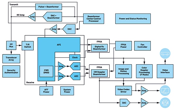 Figure 3: A more detailed block diagram of a modern ultrasound system makes its complexity more apparent, as well as the many digital functions embedded in the design. (Image source: Analog Devices)
First, there’s the power supply function. Whether the system is AC-line or battery powered, it requires multiple DC/DC regulators to develop the various rail voltages. These voltages range from a few volts for some functions to much higher voltages for the piezo transducers.
Further, as modern ultrasound systems are largely digital, except for their analog front ends for the transmit and receive paths, they include FPGAs to implement the digitally controlled beamforming and other functions. These FPGAs require a relatively significant amount of current, ranging up to 10 A.
Noise bounds performance
As with most data acquisition systems, noise is also one of the performance limiting factors for medical ultrasound systems. In addition to patient-induced speckle noise, there are various types of electronic circuit and component noise:
- Gaussian noise is statistically random “white” noise that is largely due to thermal fluctuations, or electronic circuit noise from active and passive components.
- Shot (Poisson) noise is due to the discrete nature of electrical charges.
- Impulse noise, sometimes called salt-and-pepper noise, is sometimes seen on digital images. It can be caused by sharp and sudden disturbances in the image signal and is seen as sparsely occurring white-and-black pixels, hence the informal name.
These noise sources affect image resolution and quality. They are minimized by appropriate choices of electronic components, such as low-noise amplifiers and resistors, as well as suitable analog and digital filters. In addition, some noise may be minimized in post-processing by sophisticated image and signal processing algorithms.
Regulator noise: a key factor
There is also one noise-related issue that must be addressed: switching noise from the step-down (buck) DC/DC regulators that are primarily supplying power to digital ICs, such as FPGAs and ASICs. The problem is that they also affect sensitive analog signal processing circuitry through electromagnetic (EM) radiation, as well as conduction through power rails and other conductors.
Designers attempt to minimize this noise using ferrite beads, careful layouts, and power rail filtering, but these efforts add to the component count, increase printed circuit (pc) board real estate, and are often only partially successful.
Traditionally, designers striving to minimize the noise created by the DC/DC regulators can choose an LDO with its inherently low-noise output, but relatively poor efficiency of around 50%. The alternative is to use a switching regulator with an efficiency of around 90% or higher, but with impulse noise at the output on the order of millivolts due to the switching clock.
Unlike most engineering decisions where there are tradeoffs along a continuum, the situation with DC/DC regulators requires choosing one side or the other: low noise with low efficiency versus high noise with high efficiency. There is no compromise, such as accepting 20% higher noise in an LDO in exchange for some modest increase in its efficiency.
The inherently low noise of the LDO can be compromised by another factor. Due to its relatively large size for higher current levels—primarily due to thermal concerns—it must often be placed at an extended distance from its load. This provides an opportunity for the LDO output rail to pick up radiated noise from digital components in the system, corrupting the clean rail of the sensitive analog circuitry.
One solution to LDO placement due to thermal management issues is to use a single regulator, located off to the side or corner of the pc board. Doing so helps manage the LDO dissipation issues and possibly simplifies the DC/DC system-level architecture. However, this simple-sounding solution has many problems:
- The unavoidable IR drop between the regulator and the loads due to the distance and high current levels (ΔV drop = load current (I) × trace resistance (R)) means the voltage at the loads will not be at the nominal LDO output value, and may even be different at each load. This drop can be minimized by an increase in the pc board trace width or thickness or the use of a stand-up busbar, but these use precious board real estate and add to the bill of materials (BOM).
- Remote sensing can be used to monitor the voltage at the load, but this only works well for a single-point, non-dispersed load. In addition, the remote-sensing leads may contribute to DC-rail oscillation, as the inductance of the longer supply rail and sensing leads can affect the transient performance of the regulator.
- Finally, and the problem that is often most difficult to manage, the longer power rails are also subject to more electromagnetic interference (EMI) or radio frequency interference (RFI) noise pickup.
Overcoming the EMI/RFI problem usually begins with the use of additional bypass capacitors, in-line ferrite beads, and other measures. However, the problem is often persistent. Further, this noise adds to the challenge of meeting the various regulatory mandates on noise emissions depending on its magnitude and frequency.
Silent Switcher regulators resolve the tradeoff dilemma
An alternative and usually better solution is to use individual DC/DC regulators sited as close to their load ICs as possible. This minimizes IR drop, pc board footprint, and rail-noise pickup and radiation. However, for this approach to be viable, it’s essential to have small, efficient, low-noise regulators that can be placed next to the load and still meet all of its current requirements.
This is where the many Silent Switcher regulators from Analog Devices are problem solvers. Not only do these regulators provide single-digit voltage outputs at current levels from a few amperes to 10 A, but they do so with extremely low noise, a feat accomplished through multiple design innovations.
These regulators are not a “compromise” or tradeoff positioned somewhere along the line between the low-noise attributes of LDOs and the efficiency of switching regulators. Instead, their innovative design enables engineers to get the full efficiency benefits of switchers with noise levels that are very low and close to that of an LDO. In effect, they allow designers to have the best of both attributes when it comes to noise and efficiency.
These regulators remove the conventional thinking of the LDO versus switching-regulator gap. They are available in Silent Switcher 1 (first generation), Silent Switcher 2 (second generation), and Silent Switcher 3 (third generation) devices. The designers of these devices identified the various noise sources and devised ways to attenuate each one, and each subsequent generation has yielded further improvements (Figure 4).
 Figure 4: The Silent Switcher DC/DC regulators span three generations, with each succeeding generation building on and extending the performance of its predecessor. (Image source: Analog Devices)
The benefits of the Silent Switcher 1 devices include low EMI, high efficiency, and a high switching frequency that moves much of the remaining noise away from parts of the spectrum where it would interfere with system operation or have regulatory issues. The Silent Switcher 2 benefits include all the features of Silent Switcher 1 technology, plus integrated precision capacitors, a smaller footprint, and the elimination of sensitivity to the pc board layout. Finally, the Silent Switcher 3 series exhibits ultra-low-noise characteristics in the low-frequency band from 10 Hertz (Hz) to 100 kHz, especially critical for ultrasound applications.
Due to their tiny form factor of just a few millimeters square, along with their inherent efficiency, these switchers can be located very close to the load FPGA or ASIC. This maximizes performance and eliminates disparities between datasheet performance and in-use reality.
A summary of the noise and thermal attributes of the Silent Switcher devices is presented in Figure 5.
|
Figure 5: Users of these regulators realize tangible noise and thermal benefits from the Silent Switchers’ design. (Image source: Analog Devices)
Many choices in Silent Switcher matrix
Silent Switcher regulators are available in many groups, versions, and models with different voltage and current ratings to meet the specific requirements of a system design, as well as a variety of tiny packages (Figure 6).
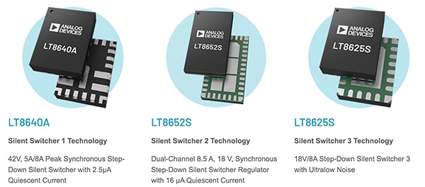 Figure 6: The many devices using Silent Switcher technology offer many permutations of voltage, current, noise, and other attributes. (Image source: Analog Devices)
The first and second-generation devices include, but are not limited to, 5-volt units with 3, 4, 6, and 10 A outputs, such as the:
- LTC3307: 5 volt, 3 A synchronous step-down Silent Switcher in a 2 mm × 2 mm LQFN package
- LTC3308A: 5 volt, 4 A synchronous step-down Silent Switcher in a 2 mm × 2 mm LQFN package
- LTC3309A: 5 volt, 6 A synchronous step-down Silent Switcher in a 2 mm × 2 mm LQFN package
- LTC3310: 5 volt, 10 A synchronous step-down Silent Switcher 2 in a 3 mm × 3 mm LQFN package
Each of these is, in turn, available in multiple versions. For example, the LTC3310 is available in four basic versions, including some that are AEC-Q100 automotive qualified. Note that both first-generation (SS1) devices—the LTC3310 and the LTC3310-1—and second-generation (SS2) devices—the LTC3310S and the LTC3310S-1—are available as adjustable and fixed output devices.
A closer look at a third-generation device, the LT8625S, highlights the features of Silent Switcher 3 designs, underscored by the outstanding low-noise performance of this 2.7-to-18-volt input, 8 A output device (Figure 7).
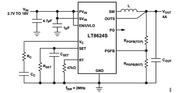 Figure 7: The LT8625S requires only a few standard external components (shown is its otherwise identical LTC8624S, a 4 A sibling). (Image source: Analog Devices)
The LT8625S features include:
- Ultrafast transient response due to its high-gain error amplifier
- A fast minimum switch on-time of just 15 nanoseconds (ns)
- A precision reference with ±0.8% drift over temperature
- PolyPhase operation supporting up to 12 phases for higher aggregate current output
- Adjustable and synchronizable clock from 300 kHz to 4 MHz
- Programmable power-good indicator
- Availability in a 20-lead 4 mm × 3 mm (LT8625SP) or 24-lead 4 mm × 4 mm LQFN (LT8625SP-1) package
Its noise performance specifications show why it is especially well-suited to ultrasound applications (Figure 8):
- Ultra-low root mean square (RMS) noise (10 Hz to 100 kHz): 4 microvolts RMS (μVRMS)
- Ultra-low spot noise: 4 nanovolts per root Hz (nV/√Hz) at 10 kHz
- Ultra-low EMI emissions on any pc board
- Internal bypass capacitors reduce radiated EMI
 Figure 8: The graphs show that both the low frequency (left) and wideband (right) noise spectral density of the LT8625S is minimal. (Image source: Analog Devices)
This low-noise performance is achieved along with high efficiency and low power loss across the entire load range (Figure 9).
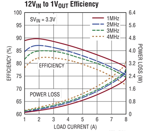 Figure 9: The high operating efficiency and low thermal impact of the LT8625S eases system design concerns. (Image source: Analog Devices)
Design-in using the 20-lead LT8625S is accelerated with the availability of the companion DC3219A demonstration circuit/evaluation board (Figure 10). The default setting of the board is 1.0 volts at an 8 A maximum DC output current. The user can change the voltage setting as needed.
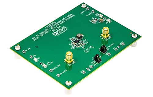 Figure 10: To enable exploration and speed design-in, the DC3291A evaluation board supports the LT8625S. (Image source: Analog Devices)
Conclusion
Ultrasound imaging systems are an indispensable, risk-free medical diagnostic tool. To achieve the required image clarity, resolution, and other performance metrics, it is critical to recognize that the received signals can be at extremely low levels, with a wide dynamic range. This requires that engineers choose low-noise components, employ prudent design techniques, and ensure that the DC power rails are as low-noise as possible.
The Silent Switcher family from Analog Devices offers the inherent high efficiency of switching DC/DC regulators while also having a noise level comparable to far-less efficient LDOs. In addition, their small size of just a few millimeters square allows them to be placed close to the loads they support, minimizing the possibility of picking up radiated circuit noise.

Disclaimer: The opinions, beliefs, and viewpoints expressed by the various authors and/or forum participants on this website do not necessarily reflect the opinions, beliefs, and viewpoints of DigiKey or official policies of DigiKey.


