The Fundamentals of Phase Locked Loop Frequency Synthesizers
Contributed By DigiKey's North American Editors
2021-02-03
Rising data rates in high-speed serial communications buses require system clocks with higher frequencies, superior stability, greater frequency resolution, and higher signal purity. Direct digital synthesizers offer these characteristics but only at frequencies below 2 or 3 gigahertz (GHz). A solution is required for frequencies of up to tens of gigahertz.
This solution begins with phase locked loop (PLL)-based analog frequency synthesizers that generate clock frequencies up to 30 GHz. Then, Integer N synthesizers (which multiply the reference frequency by an integer value) and fractional N synthesizers (which multiply the reference frequency by non-integer fractional values) employ special techniques that minimize phase noise and similar signal impurities.
This article describes the design of both integer and fractional N frequency synthesizers using example devices from Analog Devices. The article also highlights the innovations that enable these devices to be used for high-speed serial data links as well as for frequency agile radars.
Integer N phase locked loop synthesizers
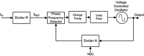
PLL circuits are used for frequency and phase control. They can be configured as clock sources, frequency multipliers, demodulators, tracking generators or clock recovery circuits. Each of these applications demands different characteristics but they all use the same basic circuit concept. Figure 1 shows a block diagram of a basic PLL configured as a frequency multiplier.
 Figure 1: Block diagram of a classical integer N phase locked loop frequency synthesizer. (Image source: DigiKey)
The operation of this circuit is typical of all phase locked loops. It is basically a feedback control system that controls the phase of a voltage-controlled oscillator (VCO). The input signal is applied to a pre-scaling divider, which divides the input frequency by a factor R. The output of the pre-scaler is the reference frequency, which forms one input of a phase-frequency detector (PFD).
The other PFD input is a feedback signal from the output of a divide-by-N counter. Normally, if the PLL is locked, the frequencies of both signals will be nearly the same. The output of the phase detector is a voltage proportional to the phase difference between the two inputs. If the loop is unlocked, as happens at startup or if there is a large instantaneous shift in the frequency of the input, then the phase-frequency detector operates to steer the PLL operating frequency to the desired setting. When that frequency is achieved, the PFD returns to phase detector mode and has an output proportional to the phase difference between the reference frequency and the feedback signal.
The phase-frequency detector drives a charge pump, which is a bipolar switched current source. This means that it can output positive and negative current pulses into the loop filter of the PLL.
The loop filter smooths the phase error signal and also determines the dynamic characteristics of the PLL. The filtered signal controls the VCO. Note that the output of the VCO is at a frequency that is N times the input supplied to the frequency reference input to the phase-frequency detector and is N/R times the frequency input. This output signal is sent back to the phase detector via the divide by N counter.
Normally the loop filter is designed to match the characteristics required by the application of the PLL. If the PLL is to acquire and track a signal, the bandwidth of the loop filter will be greater than if it were expecting a fixed input frequency. The frequency range that the PLL will accept and lock onto is called the “capture range.” Once the PLL is locked and tracking a signal, the range of frequencies that the PLL will follow is called the “tracking range.” Generally, the tracking range is larger than the capture range. The PLL loop filter also determines how fast the signal frequency can change and still maintain lock—i.e., the maximum slew rate. The narrower the loop filter bandwidth, the smaller the achievable phase error. This comes at the expense of slower response and reduced capture range. PLLs used in clock applications operate primarily at fixed frequencies. In general, the bandwidth of the loop filter should be much less than the reference frequency.
Since the PLL output frequency is an integer multiple of the reference frequency, its frequency resolution is equal to the reference frequency. Obtaining a finer frequency resolution requires decreasing the reference frequency, which is done with the pre-scale counter R.
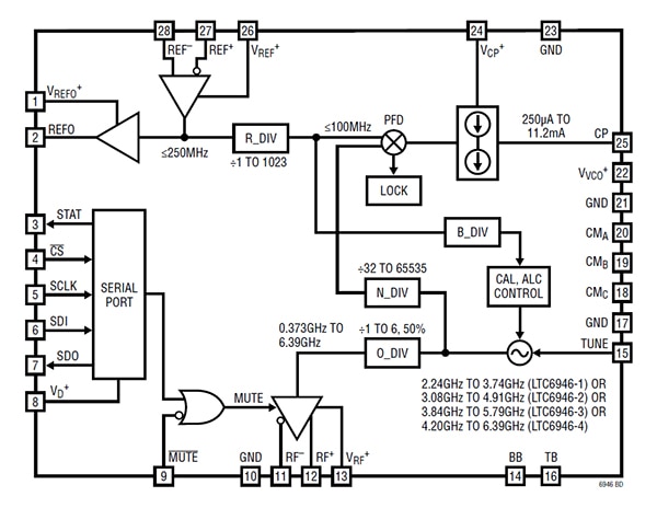
A commercial example of an integer N frequency synthesizer is Analog Devices’ LTC6946IUFD-3#PBF, a low noise 0.64 to 5.790 GHz synthesizer with an integrated VCO and excellent spurious performance (Figure 2). It is a member of a family of four synthesizer ICs, each with a different frequency range, covering a total range of 0.373 to 6.390 GHz.
 Figure 2: The block diagram of the Analog Devices LTC6946IUFD-3#PBF integer N frequency synthesizer with integrated VCO. (Image source: Analog Devices)
This synthesizer requires an external user supplied loop filter, which can be optimized for the specific application. There is an internal pre-scale counter divider with a divide range from 1 to 1023. The loop divider has a range from 32 to 65535. The charge pump current is adjustable from 250 microamperes (mA) to 11.2 milliamperes (mA) to match to the requirements of the loop filter.
Fractional N phase locked loop synthesizers
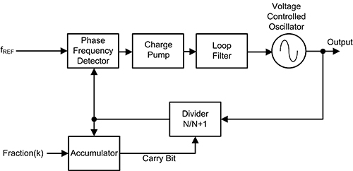
The frequency resolution of the PLL synthesizer can be improved by reducing the step size to less than integer values—i.e., making fractional steps in the loop divider (N). This is accomplished by dynamically varying or “dithering” the countdown value. This means that the divider setting holds the value N for a fixed number of cycles of the PLL output frequency and is periodically stepped to a different value, such as N+1. For example, if the divider setting is 4 for three reference periods and 5 for the fourth reference cycle, then the effective countdown is 4.25. One way to accomplish this is to use an accumulator as shown in Figure 3.
 Figure 3: The block diagram of a fractional N PLL synthesizer using an accumulator to modulate the divider count. (Image source: DigiKey)
The accumulator counts the output pulses from the divider, and every M, where M is the modulus of the accumulator, it outputs a carry bit which changes the divider input. Figure 4 continues the example of setting a fractional divider setting of 4.25.
 Figure 4: Timing diagram for a fractional N synthesizer using an accumulator. (Image source: DigiKey)
The accumulator is driven by the divided output and counts modulo four, i.e., M is equal to four. Every fourth pulse it generates a carry output, which increments the divider count by one. The accumulator resets and begins counting again. The increase in the divider setting shifts the output frequency, which results in an accumulated phase offset error. The track of phase error shows the pulse value as a function of time.
The average divider setting is 4.25, but the synthesizer output is phase modulated, resulting in spurious tones in the output. Looking at the accumulator state it is obvious that it tracks the phase error. This can be used to remove the modulation as shown in Figure 5.
 Figure 5: Using the D/A converted accumulator state to cancel the phase modulation due to the fractional N dithering. (Image source: DigiKey)
The accumulator state is converted to analog by a digital-to-analog (D/A) converter and scaled and subtracted from the phase-frequency detector output to cancel the phase modulation due to the fractional N dithering. This has to be done with great care; if the correction signal does not precisely match the phase error, then spurious tones at the output will result.
Enter the sigma-delta modulator
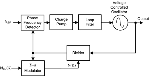
The periodicity in the accumulator is the cause of spurious outputs from the synthesizer. If the accumulator is replaced by a sigma-delta modulator, then digital techniques can be applied to modulate the divider count in a way to minimize spurious responses and noise. This replacement is shown in Figure 6.
 Figure 6: Replacing the accumulator with a sigma-delta modulator allows digital techniques to be applied to varying the divider count in order to reduce spurious responses. (Image source: DigiKey)
There are really two common digital techniques that are employed in the sigma-delta modulation topology. The first involves increasing the number of N divider counts over a wider range of values such that the average division factor will produce the desired fractional divider value. This will reduce the primary fractional spurs. The accumulator-based synthesizer varies the count between two states. This is a first order modulation method. An nth order sigma-delta fractional PLL modulates the N counter between 2n different values. For example, a third order modulator would alternate between eight different divider values, and a fourth order modulator would alternate between 16 different divider values.
The second digital technique—also referred to as dithering—involves randomizing the 2N sequence so that it is pseudorandom. While still maintaining an average fractional divider ratio, it converts the fractional spurs into shaped random noise in such a way that it can be filtered by the PLL.
A commercial version of a sigma-delta fractional N synthesizer is the Analog Devices ADF5610BCCZ, a low noise 0.57 megahertz (MHz) to 14.6 GHz fractional N synthesizer with an integrated VCO (Figure 7).
 Figure 7: A block diagram of the Analog Devices ADF5610BCCZ which supports both fractional N or integer synthesizer configurations. (Image source: Analog Devices)
The ADF5610 requires an external reference oscillator and loop filter. It has an integrated VCO with a fundamental frequency of 3650 MHz to 7300 MHz. These frequencies are internally doubled and routed to the RFOUT pin. There is a differential output that allows the doubled VCO frequency to be divided by factors of 1, 2, 4, 8, 16, 32, 64, or 128, which allows generating RF output frequencies as low as 57 MHz.
The ADF5610 uses an advanced sigma-delta modulator with a 24-bit fractional modulus that achieves exceptionally low spurious levels. As in all synthesizers using a sigma-delta modulator, this device uses digital signal processing techniques to find the desired average fractional divider ratio. This process, clocked at the PFD rate, produces output modulation noise called quantization noise with a high pass frequency response. The external low pass loop filter is used to filter this quantization noise to a level beneath the phase noise of the VCO, thus preventing the noise from contributing to the overall phase noise of the system.
The ADF5610 also includes an exact frequency mode for 0 hertz (Hz) frequency error. This mode is able to generate exact frequencies between adjacent integer N boundary steps while still using the full 24-bit phase accumulator modulus. It achieves exact frequency steps with a high phase detector comparison rate, allowing the PLL to maintain excellent phase noise and spurious performance in this mode.
The Analog Devices ADF4169CCPZ-RL7 is another PLL synthesizer that can be configured as either an integer N or a fractional N device. It operates with an RF bandwidth of up to 13.5 GHz with modulation and waveform generation. It uses an external reference frequency input, VCO, and loop filter. It has a third order sigma-delta modulator for fractional N synthesis that can be disabled, allowing the device to run in integer N mode (Figure 8).
 Figure 8: The Analog Devices ADF4169CCPZ-RL7 uses a third-order sigma-delta modulator. (Image source: Analog Devices)
The ADF4158WCCPZ-RL7 synthesizer is intended for use in frequency modulated continuous wave (FMCW) radars. It is capable of various types of modulated waveforms in the frequency domain including sawtooth and triangular ramps. This is a special feature that is necessary in radar applications.
Conclusion
Rising data rates in high-speed serial communications buses require designers to look beyond direct digital synthesizers—which work best below 3 GHz—for system clock solutions. PLL-based frequency synthesizers using integer N and fractional N topologies provide stable, low noise signals for high frequency clock, serial data communications, and radar applications for frequencies up to tens of gigahertz.

Disclaimer: The opinions, beliefs, and viewpoints expressed by the various authors and/or forum participants on this website do not necessarily reflect the opinions, beliefs, and viewpoints of DigiKey or official policies of DigiKey.


