

Understanding LED Internal Thermal Resistance
Contributed By Electronic Products
2015-09-08
Despite their superior efficacy compared with traditional lighting, LEDs still get hot. As excessive heat is a cause of undesired effects such as chromaticity shift or worse, catastrophic failure, thermal management is an important aspect of solid-state lighting (SSL) design.
For a given set of operating conditions, the LED’s internal thermal resistance primarily dictates how hot the device will get and how quickly it will reach peak temperature. Greater internal thermal resistance causes more rapid temperature rise and higher peak temperature.
This article takes a look at the definition of an LED’s internal thermal resistance and its impact on the junction temperature of commercial products.
The importance of thermal management
The primary source of heat in an LED comes from the junction between the p-type and n-type semiconductor material making up the device. This heat is a by-product of the recombination of electrons and holes at or near the junction. Ideally, recombinations result in photons that exit the LED and contribute to the overall illumination, but often the photon is reabsorbed in the die, generating heat. Tiny vibrations of the LED’s crystal lattice that occur while the device is operating also raise the temperature. Despite the high efficacy of LEDs compared to conventional light sources, some 70 to 80 percent of the electrical energy applied to the device is still converted to heat rather than light.
Because the LED junction is small, the energy density is high and the temperature rises rapidly. It is not uncommon for the junction temperature (TJ) of modern chips to rise to 100oC and above, and although contemporary LEDs are far more robust than older devices, prolonged operation at high temperatures is undesirable. Limiting junction temperature reduces chromaticity drift and prolongs life. (See the TechZone articles “Thermal Effects on White LED Chromaticity” and “Understanding the Cause of Fading in High-Brightness LEDs.”)
For a given set of operating conditions (for example forward voltage/current, density of the LED array in the lighting fixture, and typical ambient temperature) an engineer can calculate the junction temperature of an LED and design a thermal-management system to extract the heat from the chip and dissipate it safely to the surrounding environment.
Modern chips are designed with conductive heat paths to channel heat away from the junction to the “solder point.” The solder point is the part of the LED that contacts the PCB and is typically attached to the heatsinking layer of the PCB and/or a standalone heatsink (see Figure 1 [the solder point temperature is labeled as “TC” in this diagram]).

Figure 1: Modern LEDs are designed to channel heat to the solder point and then to the surrounding environment via the PCB. (Courtesy of the U.S. Department of Energy)
Manufacturers of LEDs are keen to assist their customers in overcoming the thermal management challenge. Figures 2(a) and (b) show how the paths designed into OSRAM’s TOPLED and DRAGON LED families conduct heat to the solder point.

Figure 2(a) and (b): OSRAM’s TOPLED (left) conducts heat away through one of the package’s leads while the company’s DRAGON LED uses a heat spreader. (Courtesy of OSRAM)
Some LED packages are better than others at dissipating heat and the performance of each is indicated by the device’s internal thermal resistance (Rth). Internal thermal resistance is a fundamental quality determining how hot an LED junction will get under a given set of operating conditions. Knowledge of the thermal resistance enables an engineer to calculate the junction temperature of the LEDs used in his or her design in order to ensure it will not exceed the maximum limit recommended by the chip manufacturer.
Defining thermal resistance
The internal thermal resistance for an LED is defined as:
![]()
Where RthJS = LED package thermal resistance from junction to solder point, TJ is as previously defined, TS = solder point temperature, and Q = dissipated power.
There are actually two forms of internal thermal resistance: The electrical thermal resistance and the “real” thermal resistance. The difference comes from how Q, the dissipated power, is defined. The electrical thermal resistance defines Q as supplied electrical power (i.e., forward voltage x forward current). In contrast, real thermal resistance defines Q as:
![]()
Where Pel = supplied electrical power and Popt = supplied optical power.
The real thermal resistance equation can also be written as:
![]()
Where ηLED = LED optical efficiency.
Major LED makers prefer to list the real thermal resistance in their datasheets (although there are some exceptions so engineers should be wary).
It is almost impossible to measure the junction temperature of an LED directly due to the inaccessibility of the die in a modern LED package, but measuring the temperature at the solder point and using spec- sheet data in the formula for real thermal resistance can enable an engineer to deduce its temperature.
The formula defining thermal resistance (see above) can be rearranged to:
![]()
The data sheet of a contemporary high-performance white LED such as OSRAM’s OSLON SSL LED reveals:
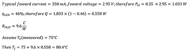
The maximum recommended junction temperature for an OSLON SSL LED is 135°C, so under these conditions the device is operating well within its limits.
Lowering thermal resistance
Reducing internal thermal resistance of an LED package makes it easier to extract heat from the device and lowers the junction temperature for given operating conditions. Alternatively, low thermal resistance allows engineers to push their devices harder without exceeding the maximum junction temperature. This offers several advantages such as requiring fewer LEDs for a given output, reducing cost, and design complexity (see the TechZone article “Maximizing LED Luminosity to Drive Down System Cost”).
Manufacturers have made significant progress in lowering their products’ thermal resistance. For example, OSRAM’s previous generation of products had internal thermal resistances of 36 to 40 C/W whereas contemporary chips such as the company’s Golden DRAGON Plus (a 71 lm/W [at 350 mA, 3.2 V] device) measures 6.5 C/W.
Cree offers a range of LEDs with low-internal thermal resistance. For example, the company’s XLamp XP-L High-Intensity LEDs (113 lm/W [at 1.05 A, 2.95 V]) have an internal thermal resistance of 2.5 C/W.
Similarly, Lumileds, Seoul Semiconductor, and Toshiba offer competitive devices. For example, Lumileds’ LUXEON Z ES chip (97 lm/W [at 700 mA, 2.8 V]) has an internal thermal resistance of 3 C/W (see Figure 3). Seoul Semiconductor offers the Z5-M1 High-Power LED (140 lm/W [at 350 mA, 2.95 V]), which features an internal thermal resistance of 4.5 C/W. For its part Toshiba offers the TL1L3 (129 lm/W [at 350 mA, 2.85 V]), which has an internal thermal resistance of 5 C/W.

Figure 3: Lumileds LUXEON Z ES has an internal thermal resistance of 3 C/W.
For more information about the parts discussed in this article, use the links provided to access product information pages on the DigiKey website.
Further reading:
- “LED Fundamentals: Internal Thermal Resistance of LEDs,” OSRAM Opto Semiconductors, July, 2011.
Disclaimer: The opinions, beliefs, and viewpoints expressed by the various authors and/or forum participants on this website do not necessarily reflect the opinions, beliefs, and viewpoints of DigiKey or official policies of DigiKey.


