Sigma-Delta Modulators Provide Tuned Feedback for Motion Control
Contributed By DigiKey's European Editors
2016-07-20
Robotics applications call for precision control over the motors that drive many of the machines' joints. The control system needs to know where the various arms and actuators are positioned to ensure reliable and safe operation. Efficiency demands also call for greater understanding of rotor movement within the motor casing on a real-time basis.

Figure 1: A generic motor control signal chain.
Without information on the rotor angle – which is prone to slippage under high loads – the control electronics may supply too much current that will simply be wasted as heat. To sense position and rotor state, an important variable for the control algorithm is the motor winding current level. Conceptually, this is an easy and low-cost variable to monitor as it simply involves providing a link from the motor to the control circuit. However, there are a number of considerations required to ensure this signal is as accurate as possible. Errors will result in loss of ability to accurately detect position and an unwanted increase in wasted energy.
The most commonly used current sensors in motor control are shunt resistors, Hall-effect sensors and current transformers. The latter two provide isolation, which is vital when dealing with high power levels, though increases overall cost. Shunt resistor circuits will generally be limited to measuring currents of 50 A or less but they have the advantage of providing the most linear response of all the sensor types, as well as lower cost. They are also suitable for both AC and DC measurements.
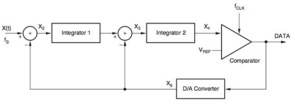
By coupling the shunt resistor with a sigma-delta modulator it is possible to achieve accurate and sensitive results. The sigma-delta sampling and filtering techniques help deal with the effects of transient noise and can support resolution well in excess of 12-bit. An example of a sigma-delta modulator designed for instrumentation applications that include motor control is the Texas Instruments ADS1203 . The device is a single-channel, second-order sigma-delta modulator intended for high-resolution A/D conversions in the DC to 39 kHz frequency range. The output of the converter is a stream of digital ones and zeroes – the time average of which is proportional to the analog input voltage. A key advantage of the use of a filtered sigma-delta modulator signal is that it shifts quantization and transient noise sources to high frequencies, making it easy to filter out using a low pass filter.

Figure 2: A typical sigma-delta bitstream responding to a change in analog input level.
By using a modulator instead of a complete A/D converter it is possible for the designer to tune the digital filtering to best suit the requirements of motor control, which include tight synchronization with the transistor switching events within the H-bridge circuit that provides power to the motor itself. The filter itself may be implemented using a digital signal processor (DSP), microcontroller or field-programmable gate array (FPGA), depending on cost and performance objectives. The use of a custom filter makes it possible to trade off transient response against final sample resolution. A higher oversampling ratio leads to greater accuracy but a lower value update rate – lowering the oversampling reduces resolution but allows a higher refresh rate.

Figure 3: A second-order sigma-delta modulator block.
In terms of data-manipulation, there is a contrast with conventional successive approximation (SAR) A/D converters. With a SAR converter, sampling is performed with the aid of a sample-and-hold circuit, which gives the system designer tight control of the timing of the sampling instant. Sigma-delta conversion, on the other hand, employs a continuous sampling process so there is no defined trigger moment for the sample. Instead, the sample at that point in time is a weighted average of a series of 1-bit samples that may straddle the value at the point in time that the sample represents.
Filtering and decimation of the 1-bit stream to a lower-rate multibit flow of samples can be done in two distinct stages but a very common approach is to use a sinc filter which can do both in one stage. A third-order, often called sinc3, is the most popular choice in these applications at the moment.
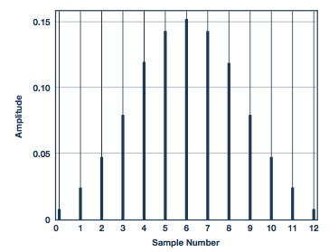
The filter is to a large extent a weighted sum of a window of samples that gives more weight to samples at the center and less weight to samples at the beginning and end of the sequence. Due to the impact of the power-transistor switching component in the measured currents, this effect needs to be taken into account or the feedback algorithm will suffer from effects such as aliasing.
The impulse response of the sinc3 filter is symmetrical with the contribution of samples ahead of the center sample being the same as those trailing it. The switching component of the current is also symmetrical around the point of average current: allowing the switching component to sum to zero. If the center of the sample window is aligned to the PWM sync pulse used to drive the H-bridge this will allow the phase current to be measured without aliasing, but care needs to be taken when data is read from the filter to ensure the sample is aligned correctly. The filtering imposes a delay such that the sample output from the filter at the time of the PWM Sync pulse will be from a number of periods before. Compared to a SAR-based current measurement this makes a difference in software-routine scheduling.
In the SAR case, the PWM-sync pulse triggers the A/D converter to perform a series of conversions. When data is ready for the control loop, an interrupt is generated and execution of the control loop can begin. With a sigma-delta modulator and filter, the samples are produced continuously but those of interest for phase-current measurement will be ready after a fixed delay. A timer or counter needs to be used to generate the interrupt once the PWM-sync signal is. The delay in terms of sample count is effectively half of the sinc3 impulse response.

Figure 4: The impulse response of a sinc3 filter.
In a typical control system, the zero-order hold effect of the PWM timer far exceeds half an impulse response so the sinc filter does not greatly affect the loop timing. With sigma-delta modulators and custom filters, the user can freely trade sinc filter latency for sample resolution. This flexibility is an advantage when it comes to design of motor control algorithms. Usually parts of the algorithm are sensitive to delay but less sensitive to the accuracy of the feedback. Other parts of the algorithm work with lower dynamics and benefit from accuracy but are less sensitive to delay.

Figure 5: Timing capture to a PWM sync signal.
Consider a proportional-integral controller (PI) algorithm. The P part and I components can operate with the same feedback signal. However, it is possible to split the P path and I path and use feedback signals with different types of filtering. In a PI controller, the main focus of the P component is to suppress the effect of rapid changes in load and speed. Therefore, it needs to be able to respond to fast changes in signal level. The I component focuses on steady-state performance with a greater emphasis on measurement accuracy. As a result, the P component can benefit from a current-feedback signal with low resolution but rapid update rate – implying a lower oversampling and decimation ratio for the sinc3 filter. The I component will benefit from a higher oversampling ratio and can withstand the resultant drop in update rate.
A further consideration in the use of sigma-delta modulators, particularly in systems that deal with larger loads, is that of isolation. One option is to simply use an isolated amplifier and employ a non-isolated modulator for A/D conversion or to place an optocoupler between the output of the modulator and the input of the device used for digital filtering. Another is to opt for an isolated sigma-delta modulator. With an isolated modulator, it is possible to dispense with analog overcurrent protection circuitry because the digital filter can also be configured to eliminate the effects of overcurrents.
One example of an isolated modulator is the AD7403 from Devices Analog. Implementing a second-order modulator, the device allows for flexible shunt size selection and provides an effective number of bits of just over 14 bits and an output stream rate of 20 MHz. With an appropriate digital filter, the device can achieve an 88 dB signal-to-noise ratio at 78.1 ksample/s. The isolation scheme uses the company’s iCoupler technology, which the company claims exceeds the performance of typical optocoupler arrangements.
Thanks to additions such as isolation and the increase in filtering performance available from a growing number of microcontrollers and programmable-logic devices, designers can continue to optimize motor control for robotics applications.

Disclaimer: The opinions, beliefs, and viewpoints expressed by the various authors and/or forum participants on this website do not necessarily reflect the opinions, beliefs, and viewpoints of DigiKey or official policies of DigiKey.


