Quickly Develop Custom, HP Test Instrumentation Using Off-the-Shelf Boards and Open Source Software
Contributed By DigiKey's North American Editors
2018-08-14
It’s often necessary to develop custom instrumentation either for experiments or for production testing. Instruments linked by GPIB/IEEE-488 and controlled by a desktop computer or workstation were an early approach. Now, more modular approaches such as PXI and PXI Express rack systems are popular. Still, such setups can get expensive, especially for one-off tests or single-use stacks.
To speed the development time and lower the cost of custom instrumentation, designers should instead consider single board instrumentation platforms with sufficient on-board analog-to-digital (ADC) or digital-to-analog (DAC) converter resources, all controlled by an embedded processor and companion FPGA.
This article will show how to develop custom instrumentation using a processor/FPGA-based system-on-module (SoM) along with supplied development tools. Drawing on a community supported, open marketplace of instrument designs, this approach to instrument development avoids the need to develop hardware and results in a compact, inexpensive tool for developing many types of instrumentation.
A brief history of instrumentation systems
Before the 1950s, all test instrumentation was analog, including voltmeters and oscilloscopes. This situation began to change when Non-Linear Systems (NLS) of Del Mar, California developed the first digital voltmeter (DVM) in 1952 using stepping relays and precision resistors. Hewlett-Packard Company’s (HP) entry into digital instrumentation was a timer/counter, which quickly became a DVM with the addition of some dual slope integration circuitry.
Because the NLS DVMs and HP digital test equipment drove internal digital displays, their readings were internally available in binary coded decimal (BCD) representation. It was a simple matter to bring these BCD signals out of the instruments on back panel connectors. Initially, these BCD signals drove printers to record the instrument readings.
In addition, many of the digital instruments that started to appear during the 1950s could be externally programmed with different measurement settings such as a measurement range. Programming took place through back panel connections wired to remote switches or relays, and eventually to external logic circuitry. Every instrument had different readout formats and programming requirements, leading to a Tower of Babel situation with respect to instrumentation automation. The problem became more complex when computers were introduced into the mix as instrument controllers during the 1960s, mainly because every instrument required a different and unique wiring scheme.
This situation led HP to start thinking about a standard digital interface for instruments during the mid 1960s. After eight years of thinking about the problem and developing a solution, HP engineers introduced the HP Interface Bus (HPIB) to the world in the October, 1972 issue of “HP Journal.” HPIB triggered the development of “rack and stack” instrumentation systems where different types of instruments from many different vendors could be interconnected to each other and to an instrument controller. Eventually, HPIB evolved into IEEE-488, and it’s still around today.
The industry learned quite a bit about automated instrumentation from HPIB systems, but test requirements outstripped the available performance from such systems. Rack and stack systems were mainly built using existing test equipment with front panel controls. These instruments were primarily intended to be used manually as standalone instruments. The front panel controls and displays added cost to these instruments, and the assumption about the measurement speeds needed by manually controlled test equipment resulted in standalone instruments that underserved the needs of many automated test systems.
As soon as instruments became fully digital, Moore’s Law ensured test equipment became both faster and less expensive. Both trends were good for automated testing, and eventually the expensive front panels became superfluous. Why have a front panel for an instrument that would always be under computer control?
The answer to this question became the next step in instrument evolution: the PXI (PCI eXtensions for Instrumentation) bus. This was introduced in 1997 and is based on the PCI interfacing standard made ubiquitous by the PC. PXI Express, based on the PCIe interfacing standard, followed in 2005. Both PXI and PXI Express support far higher data rates and much lower latency than does HPIB, permitting the development of even faster test systems.
A PXI or PXI Express chassis provides power, cooling, and a communication bus for plug-in modular instruments or I/O modules, all controlled by either a plug-in controller or an external computer. PXI and PXI Express instrumentation modules plug into these chassis, and their small front panels mostly incorporate nothing but connectors for signal inputs and outputs. PXI and PXI Express systems are significantly faster and are generally less expensive than rack and stack systems interconnected via HPIB; but they’re still relatively costly because they have good modularity, and modularity always comes at a price.
Instrumentation still rides Moore’s Law
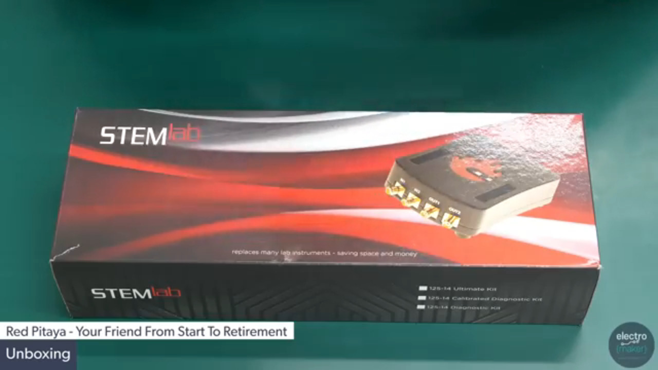
The relentless march of Moore’s Law means that instrumentation has continued to change. Just as entire board level systems have collapsed into SoCs and a handful of memory and support chips, it’s also possible to develop entire instrumentation systems that fit on a small board. Case in point: the Red Pitaya Open Instrumentation Platform that’s part of the Red Pitaya STEMlab Starter Kit 125-14 from Trenz Electronic (Figure 1).

Figure 1: The 27761 Red Pitaya Open Instrumentation Platform incorporates several analog and digital inputs and outputs that can be used to develop custom instrumentation. (Image Source: Red Pitaya)
The Red Pitaya board is based on a Xilinx Zynq Z-7010 SoC and has the following instrumentation inputs and outputs:
- Two 14-bit, 125 Ms/sec fast analog inputs
- Two 14-bit, 125 Ms/sec fast analog outputs
- Four 12-bit, 100 Ks/sec low speed analog inputs
- Four 12-bit, 100 Ks/sec low speed analog outputs
- 16 digital I/O pins
The Red Pitaya board also has a 1 Gbit Ethernet port and a USB 2.0 port. The USB port can accept a Wi-Fi dongle as well for wireless operation.
The Zynq Z-7010 SoC incorporates two Arm® Cortex®-A9 processors and a chunk of FPGA fabric on chip. The processors execute software tasks including the Red Pitaya’s embedded Linux OS and the FPGA provides real-time control and interfacing for the Red Pitaya’s on-board peripherals. Having both the FPGA and the CPU allows developers to allocate the most appropriate signal processing tasks to each for optimum performance. The FPGA can handle ultrafast and hard real-time tasks, while the CPUs excel at executing arbitrarily complex procedures, albeit more slowly. CPUs are also good for running standard operating systems such as Linux, interactive user interfaces, and Web servers.
The 27761 kit includes an SD card for the latest Red Pitaya software, a power supply, and an Ethernet cable. The software can be downloaded from the Red Pitaya site. It provides the Red Pitaya board with an embedded Linux OS and Web interface, and four initial instrument configurations: an oscilloscope, a signal generator, a spectrum analyzer, and a Bode analyzer.
The Red Pitaya site serves as a master interface for operating the Red Pitaya Open Instrumentation Platform. The Web page can download preconfigured instruments and run them. It can also initiate one of the Red Pitaya’s programming modes, including the extremely simple Visual Programming mode which uses drag and drop symbols to graphically assemble a program from icons that’s then automatically converted into Python. It’s possible to pop up the Python code created from the programming diagram.
Other alternatives for programming the Red Pitaya Open Instrument Platform include Jupyter notebooks (also based on Python), and C. Developers wanting to develop their own FPGA configurations for the Red Pitaya can use the Xilinx Vivado Tool Suite.
The Red Pitaya’s standard software also supports SCPI (Standard Commands for Programmable Instruments, pronounced “skippy”), an instrumentation control protocol originally defined as an extra layer on top of IEEE-488 and used as a control protocol for many instruments from many vendors across the industry. SCPI is independent of the hardware interface and simply consists of ASCII strings. A variety of instrumentation programming applications can control the Red Pitaya using SCPI commands, including the MathWorks’ MATLAB, National Instruments’ LabVIEW, Scilab, and Python.
The Red Pitaya hardware platform and companion software development tools serve as a foundation for development of low cost, high performance instrumentation systems, and the Red Pitaya Marketplace serves as a crossroads for people developing instrument applications for the Red Pitaya platform. There are currently nine developed instrument applications in the marketplace including:
- PID (proportional integral derivative) controller
- Network Vector Analyzer
- Software Defined Radio
- RadioBox, an integrated RF receiver and transmitter
- DSP Workbench for modeling physical systems
- Frequency Response Analyzer
- Teslameter for measuring magnetic fields
- Impedance Analyzer
- Multichannel Pulse Height Analyzer
The Red Pitaya Bazaar contains additional instrument applications written by the Red Pitaya user community including several oscilloscopes and signal generators, a power analyzer, and an impedance analyzer (Figure 2).

Figure 2: The Red Pitaya aluminum enclosure provides physical protection for the Red Pitaya board and heat sinking for the on board Zynq Z-7010 SoC. (Image source: DigiKey)
Accessories for the Red Pitaya include the:
- Trenz Electronic Red Pitaya aluminum enclosure
- Trenz Electronic Electronic Calibrated Diagnostic Kit
The Red Pitaya aluminum enclosure provides physical protection for the Red Pitaya board and heatsinking for the on-board Zynq Z-7010 SoC.
The Trenz Electronic Calibrated Diagnostic Kit includes the aluminum enclosure and adds the Wi-Fi dongle, an expansion enclosure for the Red Pitaya’s digital I/O lines, instrumentation probes, cables, connectors, and adapters for the Red Pitaya’s various ports (Figure 3).

Figure 3: The Electronic Calibrated Diagnostic Kit includes a number of accessories for the Red Pitaya including enclosures, cables, and a Wi-Fi dongle. (Image source: DigiKey)
Conclusion
Instrumentation systems have become smaller and less expensive while becoming more capable. The addition of microprocessors, and ultimately, FPGAs to the mix permits the development of very complex, custom instrumentation and test systems at relatively low cost.
The Trenz Electronic Red Pitaya Open Instrumentation Platform is an example of the current state of evolution for test systems. It provides high-speed analog inputs and outputs, and digital I/O lines all under control of two 32-bit processors and an FPGA. These can be programmed using a variety of development tools ranging from a simple visual programming language, to more conventional programming languages such as C and Python, to the Xilinx Vivado Tool Suite and FPGA programming environment.
Disclaimer: The opinions, beliefs, and viewpoints expressed by the various authors and/or forum participants on this website do not necessarily reflect the opinions, beliefs, and viewpoints of DigiKey or official policies of DigiKey.