Quickly Design Your Own Low-Cost 3D Gesture Controller
Contributed By DigiKey's North American Editors
2019-08-13
Knobs, buttons, levers, and touchscreens are typically how humans interact with machines and embedded devices. However, recent improvements in sensor technology are now opening the path for developers to add three-dimensional (3D) gesture control to their products.
Depending on the technology used, purchasing and integrating a gesture controller can be expensive. However, there are a wide variety of gesture sensor technologies available, ranging from inexpensive sensors that use infrared LEDs and photodiodes to detect movement to expensive gesture recognition cameras. Infrared gesture sensors are inexpensive, can be digitally interfaced to a low-cost microcontroller, and with a little bit of software can be sufficiently accurate for many applications.
This article explores gesture control using the Broadcom APDS-9960, an infrared (IR) gesture control sensor that can be easily integrated into nearly any embedded system.
IR-based gesture sensors
The theory behind IR-based gesture sensors is relatively simple. When detecting a hand gesture, there are several different gestures that developers might want to detect:
- Up/down
- Left/right
- Forward/backwards
In each of these cases, the sensor needs to be able to detect the direction of movement. This is done by using two main components in the sensor: a light-emitting diode (LED) and multiple directional photodiodes. Directional photodiodes are nothing more than at least four photodiodes that are positioned at a predefined distance from the IR LED. For example, the Broadcom APDS-9960 ambient light, proximity, and gesture sensor positions its photodiodes in a diamond pattern with each diode having a directional specifier such as up, down, left, and right (Figure 1).
 Figure 1: The Broadcom APDS-9960 has an integrated IR LED and four directional photodiodes that detect reflected IR energy that can be analyzed for a gesture profile. (Image source: Broadcom)
When the LED transmits infrared energy, the energy will be emitted into empty space unless there is an object, such as a hand, there to reflect it. The reflected energy will be detected by the photodiodes at different intensities depending on where the object is positioned. For example, a photodiode along the leading edge of the gesture will initially receive less reflected energy than a photodiode at the trailing edge, resulting in one photodiode having a higher count value than the other. Taking measurements over time as the gesture is made will result in the photodiodes detecting different reflected intensities at the different diodes. This stream of directional information can then be analyzed to determine the gesture.
For example, if a user were to swipe their hand from the top of the sensor to the bottom, at the start of the gesture the down photodiode would detect a larger incident reflected light than the up photodiode. As the gesture takes place, the hand moves to a point where both diodes receive an equal amount of energy. As the gesture completes, the down photodiode will receive less reflected light and the up photodiode will receive more, inverting the curve and the phase for the photodiodes (Figure 2).
 Figure 2: A downward gesture motion across the Broadcom APDS-9960 generates these photodiode curves where the leading curve indicates the gesture direction. (Image source: Broadcom)
With an understanding of how the data is generated for a gesture, the next step is to look at how to interface to the APDS-9960.
Interfacing to the Broadcom APDS-9960 gesture controller
The APDS-9960 comes in an eight-pin surface mount (SMD-8) package which takes up minimal pc board space (Figure 3). The sensor measures only 3.94 × 2.36 × 1.35 millimeters (mm). The package contains the normal power and ground pins along with an I2C interface for a digital connection to a microcontroller and pins for customizing the LED drive circuits. The package also contains an interrupt pin to notify the microcontroller when there is gesture data available for processing.
 Figure 3: The APDS-9960 comes in a compact surface mount SMD-8 package that minimizes board space. (Image source: Broadcom)
There are several different options available for building a prototype and interfacing to the APDS-9960. For example, the SparkFun APDS-9960 evaluation board provides a relatively small breakout board that includes LED drive circuits, making it ready to use out of the box (Figure 4). All a developer needs to do is solder a header in place to jumper power and ground, wire up the I2C bus and optional interrupt pin to a microcontroller, and they can start developing their embedded software. The SparkFun board also includes mounting holes so that it can be dropped into a design if using an existing board makes sense for the application.
 Figure 4: The SparkFun APDS-9960 evaluation board has all the on-board circuitry necessary to get started with gesture control. (Image source: DigiKey)
Alternatively, developers can also use the Adafruit APDS-9960 breakout board which is another all-in-one solution (Figure 5). The Adafruit breakout board is interesting because it is not only small, but it also contains an on-board 3 volt regulator that can be used to power additional circuitry such as a power LED or even a low-power microcontroller. On top of that, Adafruit provides developers with an entire Adafruit APDS9960 breakout user guide, along with several software libraries for connecting to Arduino boards or development boards that run Python. This makes using the APDS-9960 a great out of the box experience and can dramatically decrease the amount of time a developer spends getting started with the sensor.
 Figure 5: The Adafruit APDS-9960 breakout board includes the APDS-9960 along with an on-board 3 volt regulator and I2C voltage translation circuits to support 3 volt or 5 volt buses. (Image source: DigiKey)
The easiest way to interface either of these breakout boards is to solder Molex 22-28-4255 breakaway headers to the boards. This is best done with the headers facing down to provide several advantages. First, it allows the board to be plugged into a breadboard like the Digilent 340-002-1 solderless breadboard kit (Figure 6). Second, it keeps the top surface of the board clear, providing plenty of room for a hand to make gestures without accidentally catching wires hanging off the headers.
 Figure 6: The Adafruit APDS-9960 breakout board soldered and prepared on a Digilent Solderless Breadboard. (Image source: Adafruit)
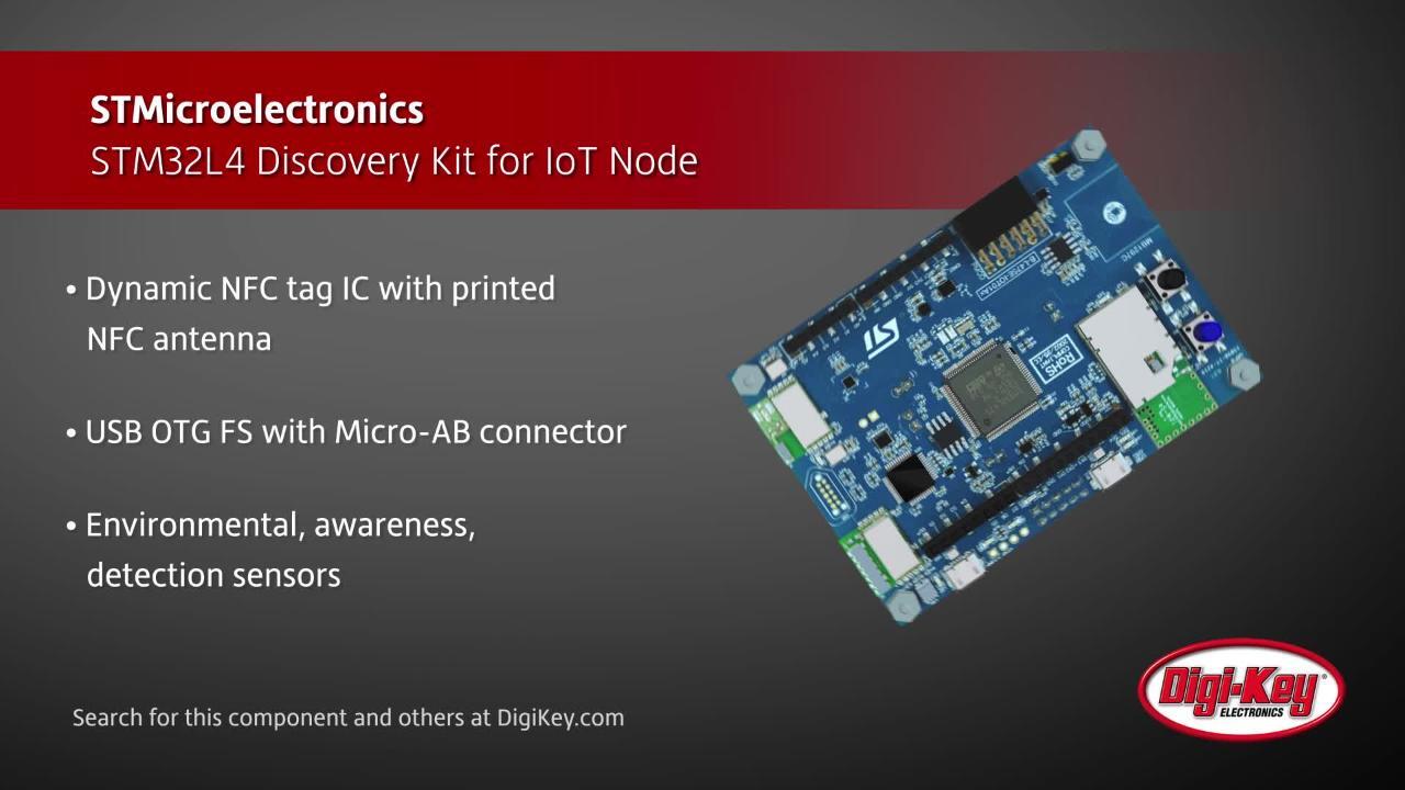
At this point, power and ground need to be wired, and the I2C lines need to be wired to the desired microcontroller development board. Any development board with a microcontroller on it can be used. However, a good choice is STMicroelectronics’ B-L475E-IOT01A2 STM32L475 IoT Discovery Kit for IoT Node (Figure 7). This development board has Arduino headers and is also supported by MicroPython, which can be programmed on the board with minimal effort. Once that is done, Python scripts can be used to interface with the gesture sensor, further making gesture control not just feasible, but nearly trivial.
 Figure 7: The STM32L475 Discovery Kit for IoT Node includes Arduino headers that can be easily interfaced to the APDS-9960 breakout boards. (Image source: STMicroelectronics)
Detecting gestures using Python
Obtaining gesture data from the APDS-9960 is not complicated, but it does require a developer to read through the datasheet carefully. The APDS-9960 has several different capabilities that include the following:
- Gesture sensing
- Ambient light sensing
- RGB color sensing
- Proximity sensing
These are all controlled through a state machine that executes based on how the registers are set up for the application. For example, a great technique to prevent the gesture engine from executing all the time is to use the proximity sensing engine to detect when a hand is present. Once the reflected IR energy reaches a preset count, the proximity engine state will transition to the gesture engine, which will measure the directional photodiodes and place the measured value into a first-in, first-out (FIFO) buffer. In order to enable this capability, the control register needs to be set to enable proximity, and a count threshold needs to be set.
Depending on the gestures needed by the application, a developer may need to write algorithms to detect specific gestures. However, for common gestures such as up/down and left/right, developers can leverage the Adafruit APDS-9960 CircuitPython library. After the library is copied to the Python device, it can be imported using the code shown in Listing 1. This code imports the APDS-9960 library along with several libraries that support the I2C bus.
Copy
import board
import busio
import adafruit_apds9960.apds9960

i2c = busio.I2C(board.SCL, board.SDA)
sensor = adafruit_apds9960.apds9960.APDS9960(i2c)
Listing 1: The CircuitPython imports and library initialization code to interface with the APDS-9960 gesture controller. (Image source: Adafruit)
The sensor object is an instance of the APDS-9960 library. We will see in just a moment that it is very easy to use. In order to enable gestures, a developer only needs to enable the gesture feature using the following code:
Copy
sensor.enable_gesture = True
The main program loop setup to read the gesture is itself just a few lines of code (Listing 2).
gesture = sensor.gesture()
while gesture == 0:
gesture = sensor.gesture()
print('Saw gesture: {0}'.format(gesture))
Listing 2: Detecting a gesture is as simple as making the call to a single library method repeatedly. (Image source: Adafruit)
As you’ll notice from reading this code, if a gesture is seen, the gesture detected will be printed to the screen (Figure 8).
 Figure 8: Example gesture output result from the Adafruit APDS-9960 CircuitPython library. (Image source: Adafruit)
The gesture output is given by a number, which can be easily converted using the following key:
0 = No gesture detected
1 = Up gesture detected
2 = Down gesture detected
3 = Left gesture detected
4 = Right gesture detected
As shown, leveraging a pre-existing library can make basic gesture recognition easy using just a few lines of code. More complex gestures would require modifying the library to analyze the raw gesture data.
Tips and tricks for creating a gesture controller
Building and integrating a gesture control sensor in a product isn’t without a few challenges. Here are a number of “tips and tricks” that developers need to consider when working with infrared-based gesture controllers:
- Use the gesture sensor’s internal proximity detector to trigger the gesture control engine in order to minimize invalid gesture starts.
- Start with an existing gesture library and build additional gestures on top of the capabilities that already exist.
- Adjust the gain on the photodiodes to values that best fit the end gesture application.
- Adjust the LED output drive intensity to values that best fit the application. This may require some tweaking in order to get repeatable results.
- A developer should start any gesture application development with high level software development until they understand the sensor and then move to lower level code.
Following these tips will help ensure that developers minimize the time that they spend getting an IR gesture controller up and running.
Conclusion
There is a steady push to start interacting with machines in a more natural and intuitive way, and one leading option is to use gesture control technology. While there are many different types of gesture control technologies, the lowest cost and easiest to work with is an infrared-based gesture sensor. As shown, integrating a gesture sensor with a microcontroller doesn’t need to be a time-consuming activity provided developers leverage existing hardware and software technologies.
Disclaimer: The opinions, beliefs, and viewpoints expressed by the various authors and/or forum participants on this website do not necessarily reflect the opinions, beliefs, and viewpoints of DigiKey or official policies of DigiKey.