Know Your Breadboards and Prototype Boards to Ensure a Smooth Project Start
In the dark ages—before the mass availability of computers and circuit simulation software—electronics designers went from the drawing board to a breadboard to evaluate a circuit’s performance. Even today, despite Spice simulation and its variants, there are some circuits that you have to prototype. For example, Spice will not tell you how an audio circuit sounds, so you have to breadboard it.
In my youth, the word breadboard connoted a literal board, perhaps even a cutting board from the kitchen (Figure 1).
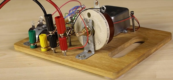 Figure 1: An example of a breadboard prototype of the past. Components are screwed to a wooden board, and nails serve as connection points. (Image source: Bud Industries)
Luckily, we can spare Mom’s cutting board and use either solderless breadboards or prototype printed circuit boards (pc boards). A good example of a solderless breadboard terminal strip is Bud Industries’ BB-32621, measuring 3.2 inches (in.) x 2.08 in. (Figure 2).
 Figure 2: The BB-32621 is an example of a small solderless breadboard terminal strip. (Image source: Bud Industries)
The board is arranged as four horizontal power strips running the length of the board to distribute power (+) and negative power or ground (-). Shorter, vertical strips run across the board width. These are tie points for components. A central channel with a width suitable for most through-hole ICs separates the tie-point busses (Figure 3).
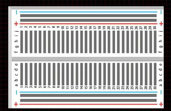 Figure 3: An interior view of the BB-32621 shows the arrangement of the power-strip conductors and tie-point conductors. (Image source: Bud Industries)
The hole spacing on the breadboard is 0.1 in. (2.54 millimeters (mm)), matching the spacing on most through-hole ICs. The solderless terminal strip has 400 possible tie points—300 for component tie-point connections and 100 for power-distribution connections. ICs are positioned horizontally over the central channels (Figure 4).
 Figure 4: A simple 555 timer circuit and the corresponding breadboard layout. (Image source: Bud Industries)
Given that through-hole ICs are going away and surface-mount devices (SMD) are becoming the norm, you may need a socket adaptor to mate an SMD to a solderless breadboard. The Logical Systems Inc. PA-SOD3SM18-16 is an example of a surface-mount-to-DIP package adaptor (Figure 5).
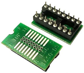 Figure 5: The PA-SOD3SM18-16 adapts a SOIC IC to a 16-pin DIP package with 0.1 in. pin spacing that is suitable for a solderless breadboard. (Image source: Logical Systems Inc.)
For larger projects, you can use solderless breadboards like Digilent Inc.’s 340-002-1, a 9.06 in. x 6.89 in. (230 x 175 mm) frame-mounted breadboard (Figure 6).
 Figure 6: The 340-002-1 is a larger solderless breadboard for bigger projects that comes mounted on a steel frame. (Image source: Digilent Inc.)
The 340-002-1 is a composite breadboard with three 630 tie-point terminal strips and five 100-point distribution strips, all mounted on a steel backing plate. Four binding posts are included for power and ground connections.
These solderless breadboards are ideal for educational projects and low-frequency circuits. They are not good for high-frequency circuits or digital circuits with fast transition times due to the large parasitic inductance and capacitance caused by the large conductors used. These types of projects are best built on prototype pc boards, like Bud Industries’ EXN-23404-PCB (Figure 7).
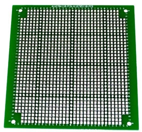 Figure 7: Shown is a typical printed circuit prototype board where components are soldered to the board’s grid array of holes. (Image source: Bud Industries)
This prototype pc board measures 4.02 in. x 3.87 in. (102.1 x 98.3 mm) and is constructed using FR4 epoxy glass that is 0.063 in. (1.6 mm) thick. It has a plated, through-hole grid array with 0.051 in. (1.3 mm) diameter holes on 0.1 in. (2.54 mm) centers. This type of prototype board minimizes stray reactance, and wiring can be very short due to the close proximity of the holes. Ground planes can be synthesized by soldering copper foil over selected areas of the pc board. As in the case of the solderless breadboards, surface-mount ICs can be added using adaptors that mate the IC to the 0.1 in. hole pattern.
Conclusion
Shown are some of the simple and common approaches to creating circuit prototypes. They are certainly easier to use compared to creating and manufacturing a pc board layout and can be very helpful in learning about your circuit. Still, you must be aware of their limitations.

Have questions or comments? Continue the conversation on TechForum, DigiKey's online community and technical resource.
Visit TechForum


