How to Use Optical Interconnects to Optimize Datacenter Performance
Contributed By DigiKey's North American Editors
2023-03-02
The need for high speed, low power, and robust fiber optic interconnects is growing to support the demands for reliable and low latency communications in cloud and other datacenters. Fiber optic transceivers can be optimized to meet specific datacenter needs for transmission speeds to 400 Gigabits/second (G). Important module standards for fiber optic datacenter communications include small form factor pluggable (SPF), SPF+, and quad small form-factor pluggable (QSFP). One of the differences between SPF, SPF+, and QSPF is rated transmission speed. Still, that’s only one factor to consider when selecting a transceiver; power consumption and thermal management, required transmission distance, operating temperature range, integrated diagnostics, and other factors must be weighed. In addition, network engineers need an effective way to test optical transceivers’ transmission range and receiver sensitivity.
This article begins by reviewing important considerations when selecting fiber optic transceivers, compares the hardware interface options provided by SPF, SPF+, QSFP, and QSFP-DD (double density), and presents transceiver modules from Intel Silicon Photonics, II-VI, and Cisco Systems. It closes with a look at fiber optic device testing, including a loopback module from ColorChip for 400 G devices and an evaluation board from Multilane for next-generation 800 G transceivers.
Single- vs. multi-mode
Optical fibers for data communication consist of a glass core encased in a glass cladding, each with different indices of refraction. Typical multi-mode (MM) fibers have a 50 μm core and operate with 750 nm to 850 nm wavelengths, while a single-mode (SM) fiber has a 9 μm core and typically operates with 1310 nm to 1550 nm wavelengths. In the case of MM fibers, the wavelength of the light is shorter than the cutoff wavelength, resulting in multiple modes of light propagating down the fiber. The smaller core in SM fiber can only propagate one mode for a specified wavelength (Figure 1).
 Figure 1: The small core in SM fibers restricts their ability to transmit light in more than one mode. (Image source: Cisco)
Modal dispersion and modal noise limit the bandwidth of MM fibers compared with SM fibers that are not subject to those effects. In addition, SM fibers can support much longer transmission distances compared to MM fibers. Optical transmission of data is achieved by using a different wavelength for each direction of the communication. For example, one set of optical transceivers uses a combination of 1330 nm and 1270 nm wavelengths. One of the transceivers transmits a 1330 nm signal and receives a 1270 nm signal, while the other transceiver transmits a 1270 nm signal and receives a 1330 signal (Figure 2).
 Figure 2: Optical transceivers use different wavelengths for transmitting and receiving data. (Image source: Cisco)
Power and thermals
Datacenter operators are sensitive to power and thermal costs. While unshielded twisted pair (UTP) for data communications cabling is inexpensive, a UTP transceiver may consume about 5 W of power compared with 1 W or less needed by a fiber transceiver.
The additional heat generated by UTP transceivers must be removed from the datacenter, doubling the overall energy cost increase to almost ten times. Except for very short runs and low data rates, fiber transceivers are almost always less expensive in total lifetime operating costs compared with UTP solutions.
UTP cables are also larger in diameter compared with fiber cabling. They can be too large to fit in some cable trays installed under the floor in high-density datacenters. In addition, for Cat 6A cables transmitting at 10 G, cross-talk between UTP cables can be difficult to manage. MM fiber uses lower-cost transceivers, but the cabling is more expensive when parallel optics are used for 40 or 100 G transmissions. As data rates continue rising, SM fiber may offer the best combination of low power, low cost, and small solution sizes.
Temperature range choices
Datacenters are found in various environments, from dedicated facilities to closets in offices, warehouses, and factories. Fiber optic transceivers are available in three standard temperature ranges to meet the needs of specific environments:
- 0°C to +70°C, called C-temp or COM, are designed for commercial and standard datacenter environments.
- -5°C to +85°C, called E-temp or EXT, for use in more challenging environments.
- -40°C to +85°C, called I-temp or IND, for use in industrial installations.
A typical optical transceiver is expected to operate with a case about 20 degrees hotter than the ambient temperature. In environments where the ambient exceeds +50°C or falls below -20°C, IDN-rated transceivers are used. Some applications require transceivers that can ‘cold start.’ During cold start operation, the network can access the transceivers’ I²C and other low-speed interfaces, but data traffic does not start until the case temperature reaches -30°C. To ensure reliable network operation, it’s important to monitor the operating temperature of fiber optic transceivers.
Digital optical monitoring
Digital optical monitoring (DOM), also referred to as digital diagnostic monitoring (DDM), is defined in SFF-8472, part of the multi-source agreement (MSA) focused on the digital monitoring of fiber optic transceivers. It includes the following capabilities:
- Monitoring module operating temperature
- Monitoring module operating voltage
- Monitoring module operating current
- Monitoring transmit and receive optical power
- Issue an alarm if parameters exceed safe levels
- Provide module factory information upon request
DOM, as specified by SFF-8472, defines specific alarm flags or alarm conditions. DOM helps network administrators monitor module performance and identify modules that may need to be replaced before they fail.
Up to 100 G, optical transceiver modules have been managed over an I²C control interface using a basic memory-mapped command system defined by SFF 8636. Higher speed modules are more complex to manage due to the inclusion of PAM-4 interfaces that need complex equalization. The Common Management Interface Specification (CMIS) was developed to replace or supplement SFF-8472/8636 in high-speed modules.
Form factors and modulation schemes
SFP transceivers are available for copper and fiber networks. Using SFP modules enables individual communications ports to be populated with different types of transceivers. The SFP form factor and electrical interface are specified in the MSA. A basic SFP transceiver can support data rates up to 4 G for Fibre Channel. The newer SFP+ specification supports up to 10 G, and the latest SFP28 specification supports up to 25 G.
The larger QSFP transceiver standard supports transmission speeds four times faster than the corresponding SFP units. The QSFP28 variant delivers up to 100 G while the QSFP56 doubles that to 200 G. A QSFP transceiver integrates four transmit and four receive channels, ‘28’ means that each channel (or lane) can support data rates up to 28 G.; as a result, a QSFP28 can support a 4 x 25 G configuration (breakout), 2 x 50 G breakout, or 1 x 100 G depending on the transceiver. Since QSFP ports are larger than SFP, adapters are available, allowing an SFP transceiver to be placed in a QSFP port.
The latest variation is the QSFP-DD which doubles the number of interfaces compared to a regular QSFP28 module. In addition, the new specification includes support for pulse amplitude modulation 4 (PAM4) that can deliver 50 G, providing an additional doubling of transmission speed and resulting in an overall 4-times increase in port speed compared to a QSFP28 module.
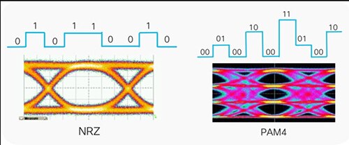
Traditional non-return to zero (NRZ) modulation used in fiber transceivers modulates the intensity of the light at two levels. PAM uses four light intensity levels to encode two bits in each optical pulse period instead of one, enabling almost double the data in the same bandwidth (Figure 3).
 Figure 3: More complex PAM4 transmissions carry much more data than NRZ. (Image source: Cisco)
QSFP-DD for large datacenters
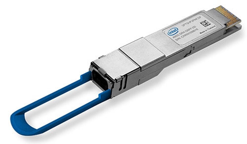
Designers of large-scale cloud and enterprise datacenters can turn to the SPTSHP3PMCDF QSFP-DD optical transceiver from Intel Silicon Photonics. This module has a 2 km transmission capability, is specified for operation from 0°C to +70°C, and supports 400 G optical links over SM fiber or four 100 G optical links for breakout applications (Figure 4). Features of this QSFP-DD transceiver include:
- Compliance with 4 x 100 G Lambda MSA optical interface specification and the IEEE 400GBASE-DR4 optical interface standard
- IEEE 802.3bs 400GAUI-8 (CDAUI-8) electrical interface standard compliance
- CMIS management interface standard compliance with full module diagnostics and control through I²C
 Figure 4: This QSFP-DD transceiver has a 2 km range. (Image source: Intel)
Multi-mode SFP+
The FTLF8538P5BCz SFP+ optical transceiver from II-VI has integrated DDM functions and is designed for use in 25 G data rate over MM fiber (Figure 5). It’s designed to operate from 0°C to +70°C. Other features include:
- 850 nm vertical cavity side emitting laser (VCSEL) transmitter
- 100 m transmission over 50/125 μm OM4, M5F MMF cable
- 70 m transmission over 50/125 μm OM3, M5E MMF cable
- 1E-12 bit error rate (BER) over 30 m with OM3 cable and 40 m with OM4 cable
- 1 W maximum power consumption
 Figure 5: This SFP+ transceiver is rated for 25 G and uses MM fiber. (Image source: II-VI)
SPF single-mode
The SFP-10G-BXD-I and the SFP-10G-BXU-I from Cisco operate with SM fiber that supports transmission distances up to 10 km. An SFP-10G-BXD-I is always connected to an SFP-10G-BXU-I. The SFP-10G-BXD-I transmits a 1330-nm channel and receives a 1270-nm signal, and SFP-10G-BXU-I transmits at a 1270-nm wavelength and receives a 1330-nm signal. These transceivers also include DOM functions that monitor performance in real-time.
Loopbacks for testing
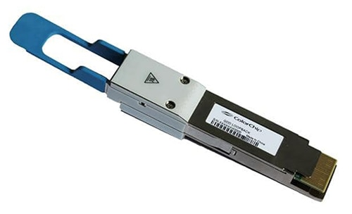
Network and test engineers and technicians can use fiber optic loopbacks and loopback modules to test optical network equipment’s transmission capability and receiver sensitivity. ColorChip provides a loopback module that supports high usage scenarios with 2000 cycles at -40°C to +85°C (Figure 6). This loopback module includes software-defined multiple power consumption to emulate the optical module power and the embedded insertion loss characteristics emulating real-world cabling for 200/400 G Ethernet, Infiniband, and Fibre Channel. The built-in surge current protection mitigates the risks of damaging the tested device. Uses of this loopback module include port testing, field deployment testing, and equipment troubleshooting.
 Figure 6: This loopback module is designed to test optical transceiver performance. (Image source: DigiKey)
800 G QSFP dev kit
For network engineers preparing for the next generation of 800 G transceivers, Multilane offers the ML4062-MCB which provides an efficient and easy-to-use platform for programming and testing QSFP-DD800 transceivers and active optical cables (Figure 7). The GUI supports all features defined by QSFP-DD MSA and simplifies the configuration process. It can be used to simulate an actual environment for QSFP-DD transceivers module testing, characterization, and manufacturing and complies with the OIF-CEI-112G-VSR-PAM4 and OIF-CEI-56G-VSR-NRZ specifications.
 Figure 7: This dev platform is designed for use with next-generation 800 G transceivers. (Image source: DigiKey)
Summary
Fiber optic transceivers support datacenter network engineers’ needs for high-speed, compact, and low power solutions. These transceivers are available in various formats and three standard operating temperature ranges, with either SM or MM fibers. Loopback modules can be used to validate the performance of fiber optic network elements. Development platforms can be used to explore the capabilities of 800 G transceivers and prepare the way for the next generation of fiber-based networks.

Disclaimer: The opinions, beliefs, and viewpoints expressed by the various authors and/or forum participants on this website do not necessarily reflect the opinions, beliefs, and viewpoints of DigiKey or official policies of DigiKey.


