How to Implement Hybrid Control Networks in Industrial Applications
Contributed By DigiKey's North American Editors
2022-12-14
Industrial complexes like oil and gas refineries, chemical plants, liquid natural gas terminals, and similar facilities are massive and are challenged to improve operational efficiencies, support flexible production, reduce costs, and ensure secure and safe operation. The continuous nature of the production processes heightens the challenges. To ensure optimal operation, industrial control networks in these facilities must constantly monitor temperature, pressure, vibration, flow, and other parameters at thousands of locations. Networks can extend over several kilometers (km) and require various copper and fiber optic data communications technologies to support a range of devices, from low bandwidth sensors to higher bandwidth real-time controls and safety devices.
To achieve these diverse requirements, network engineers need to deploy an optimal mix of copper and various types of fiber optic communications devices, all connected with compact Industrial Ethernet switches with redundant power sources, wide operating temperature capabilities, remote monitoring, and advanced security features.
This article begins with a brief overview of Industrial Ethernet (IE), including the need for hybrid fiber/copper data communications networks with a particular focus on fiber optics. It compares single mode (SM) and multimode (MM) fibers, looks at hot-pluggable fiber optic module standards and how digital diagnostic monitoring (DDM) of fiber optic modules works, and then presents a range of fiber optic data communications devices from Cisco Systems, Phoenix Contact and Intelligent Network Solutions, along with a managed Industrial Ethernet switch with a mix of copper and fiber optic ports in a hardened IP40 enclosure from Red Lion Controls.
IE is based on the use of Ethernet protocols with extended temperature range switches, and rugged interconnects to withstand harsh environments. IE can support real-time control and determinism and is implemented using a range of communications protocols like EtherCAT, EtherNet/IP, PROFINET, and Modbus TCP.
IE networks are expected to provide some level of interoperability between legacy and current systems and still produce predictable performance and be easily maintained to maximize uptime. A combination of copper and fiber optic interconnects is often used in large facilities. When appropriate, copper can provide a lower-cost alternative. However, using fiber optics can reduce problems associated with electrical noise, provide electrical isolation, and support much longer interconnect lengths that can be particularly useful in large and dispersed industrial complexes.
MM vs. SM fiber
Light travels down an optical fiber because the optical index mismatch between the core and cladding causes total internal reflection. The diameter of the core is critical and defines the cone of acceptance containing the angles at which light entering the fiber can continue to propagate. SM fiber uses a small 10 micrometer (µm) core that can support only one mode of propagation, called the fundamental mode. MM optical fibers have large core diameters relative to the light’s operating wavelength. Those larger cores simultaneously guide many modes, also called standing-wave patterns, of light (Figure 1). The ISO/IEC 11801 standard defines five classes of MM fiber based on two core sizes and various bandwidth characteristics: OM1, OM2, OM3, OM4, and OM5. Fiber optic cables can be categorized based on the core’s and cable’s diameter. For example, 62.5/125 µm refers to OM1 MM. 50/125 µm cables are used for OM2, OM3, OM4, and OM5 MM, and 10/125 µm is an example of a SM cable.
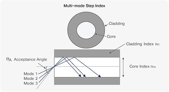 Figure 1: MM fibers are relatively large in diameter and can support the transmission of many modes of light at the same time. (Image source: Cisco Systems)
MM fibers can be operated with light emitting diode (LED) sources, but higher-performance designs use vertical cavity surface emitting lasers (VCSELs). Using VCSELs enables MM fiber networks to deliver multi gigabit data rates.
The five categories of MM fibers are based on light wavelength (in nanometers, nm), core diameter in μm, and modal bandwidth. Modal bandwidth is a measure of the maximum signal rate in megahertz (MHz) for a given distance in km, or the maximum distance for a given signaling rate, and is the product of the bandwidth and distance, MHz·km. For a given cable, when the distance is cut in half, the maximum signaling rate doubles. The MM fiber classes defined by ISO/IEC 11801 are:
- OM1: 62.5 μm core with a minimum modal bandwidth of 200 MHz·km at 850 nm
- OM2: 50 μm core with a minimum modal bandwidth of 500 MHz·km at 850 nm
- OM3: 50 μm core with a minimum modal bandwidth of 2000 MHz·km at 850 nm
- OM4: 50 μm core with a minimum modal bandwidth of 4700 MHz·km at 850 nm
- OM5: 50 μm core with a minimum modal bandwidth of 4700 MHz·km at 850 nm and 2470 MHz·km at 953 nm
The OM3 standard was designed to support the IEEE 802.3 10GbE Ethernet standard. When used with VCSEL modulation, OM3 MM cables can deliver 10 gigabits per second (Gb/s) at distances up to 300 meters (m). In most instances, OM3 MM fiber links are the most cost-effective solutions for applications up to about 500 m. OM4 MM links can support distances up to 1 km. For longer distances and higher data rates, SM fibers are needed.
SFP for copper and fiber
The small form-factor pluggable (SFP) interface is a compact, hot-pluggable network module format used for data communications and telecommunication networks. An SFP interface on networking hardware like an Ethernet switch is a modular slot for a media-specific transceiver, such as a copper or fiber optic cable. SFPs enable ports to be equipped with different types of transceivers as needed. The SFP replaced the previously developed and larger gigabit interface converter (GBIC) and is sometimes called the “mini-GBIC”. The Small Form Factor Committee has specified the form factor, mechanical interlocks, and electrical interfaces through a multi-source agreement, the MSA SFF-8472 (Figure 2). In addition to standard SFP interfaces, higher speeds can be achieved using SFP+ for up to 10 Gbit/s and SFP28 for speeds of 25 Gbit/s.
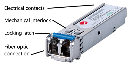 Figure 2: Mechanical elements of a fiber optic SPF module highlighting the latching and interlock mechanisms and the fiber optic and electrical connections. (Image source: Intelligent Network Solutions and Jeff Shepard)
SFP fiber optic transceivers are available that support synchronous optical networking (SONET), Gigabit Ethernet, Fibre Channel, passive optical networking (PON), and other communications standards.
Digital diagnostic monitoring
The MSA SFF-8472 also defines the DDM functions for fiber optic transceivers. DDM is sometimes called digital optical monitoring (DOM). DDM lets network administrators monitor optical input/output power, temperature, laser bias current, and transceiver supply voltage in real-time (Figure 3). DDM is an expansion of the serial ID interface defined in GBIC specification. DDM includes alarms and warning flags that send alerts if operating parameters are outside a factory setting for normal operation.
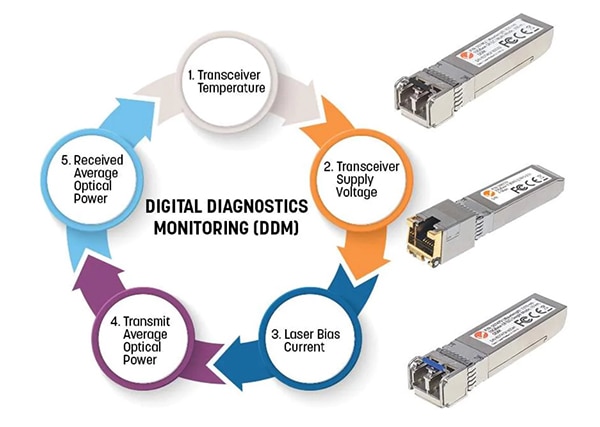 Figure 3: DDM can monitor the performance of SFP optical transceivers and send alerts if any parameters fall outside of nominal operating ranges. (Image source: Intelligent Network Solutions)
DDM is designed to help predict failures and support preventative maintenance for maximum network uptime. The transceiver maker sets DDM thresholds for various parameters. Operating the transceiver beyond any thresholds will result in degraded performance and potentially cause transmission errors. The transceiver sends an alarm when a parameter’s value exceeds a specified threshold. In addition, the module will stop transmitting data, and the receiver will refuse to receive any messages. It’s not uncommon for multiple alarms to be issued at once; for example, if the transmit optical power is too high, the temperature may also be high.
While DDM will shut down and protect the system when preset thresholds are exceeded, it can also be used to monitor the operating parameters of the transceiver and let operators see values that are moving in the wrong direction before they exceed damaging levels, enabling preventative maintenance to be scheduled.
MM fiber and 1 km range
Industrial control network designers can use the 2891754 Gigabit SFP module from Phoenix Contact to support transmissions up to 1 km using fibers designed to operate with a wavelength of 850 nm (Figure 4). This module is suited for industrial applications and has an operating temperature range of -40 to 85 °C and up to 95% humidity. The transmission distance depends on the fiber used:
- 275 m with 62.5/125 µm (OM1)
- 550 m with 50/125 µm (OM2)
- 800 m with 50/125 µm (OM3)
- 1000 m with 50/125 µm (OM4)
 Figure 4: This SFP optical transceiver has a range of 1 km when operating with a wavelength of 850 nm and an OM4 cable. (Image source: DigiKey)
20 km range with SM fiber
Intelligent Network Solutions’ INT 506724 SFP module supports 1000Base-LX data transmissions up to 20 km over a single-mode 9/125 µm fiber using a 1310 nm laser. It supports DDM, and the metal housing reduces electromagnetic interference (EMI) and increases durability (Figure 5). It has an operating temperature range of 0 to 70 °C and is specified for 10 to 85% relative humidity (RH).
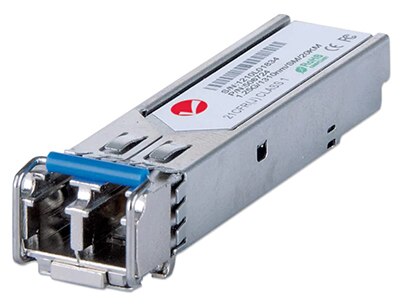 Figure 5: Intelligent Network Solutions’ INT 506724 SFP module supports 1000Base-LX data transmissions up to 20 km over a single-mode 9/125 µm fiber using a 1310 nm laser. (Image source: Intelligent Network Solutions)
10 km SFP transceivers
The SFP-10G-BXD-I and the SFP-10G-BXU-I from Cisco operate with SM fiber, and support transmission distances up to 10 km when plugged into an SFP+ port. These transceivers feature optical interoperability with 10GBASE XENPAK, 10GBASE X2, and 10GBASE XFP interfaces on the same link and include DOM functions monitoring real-time performance. When used, an SFP-10G-BXD-I always connects to an SFP-10G-BXU-I. The SFP-10G-BXD-I transmits a 1330-nm channel and receives a 1270-nm signal, and SFP-10G-BXU-I transmits at a 1270-nm wavelength and receives a 1330-nm signal (Figure 6).
 Figure 6: These optical transceivers use different wavelengths for transmitting and receiving data. (Image source: Cisco Systems)
Industrial Ethernet-managed switch
Network engineers that need a 12-port managed Gigabit Ethernet switch that features eight ports with four SFP combination ports, and Modbus monitoring can turn to the Sixnet SLX-8MG-1 from Red Lion. The SLX-8MG-1 features eight 10/100/1000Base-T(X) ports with four SFP combo ports (supporting 100Base or 1000Base fiber transceivers). The SLX-8MG is housed in a slim, hardened metal DIN-rail enclosure for use in challenging industrial environments and supports redundant 10-30 VDC power inputs and a -40 to 75 °C operating temperature range. It also includes Modbus/TCP remote monitoring, advanced security features, extended shock and vibration capability, and high electrical noise and surge immunity levels.
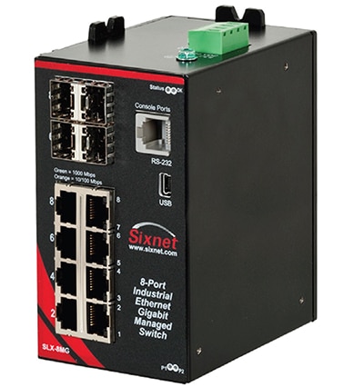 Figure 7: The SLX-8MG-1 managed Gigabit Ethernet switch features eight 10/100/1000Base-T(X) ports with four SFP combo ports (top left). (Image source: Red Lion)
Conclusion
Hybrid fiber optic and copper networks can help to improve operational efficiencies, support flexible production, reduce costs and ensure secure and safe operation in large-scale industrial operations like oil and gas refineries and chemical plants. Network engineers can use managed Gigabit Ethernet switches to deploy a mix of fiber optic and copper communications links. Using MM and SM fibers supports optimal modal bandwidths and including DDM capability enables preventative maintenance to ensure maximum network uptime.

Disclaimer: The opinions, beliefs, and viewpoints expressed by the various authors and/or forum participants on this website do not necessarily reflect the opinions, beliefs, and viewpoints of DigiKey or official policies of DigiKey.


