How to Quickly Boost Power Transfer from USB-C Devices to 100 W with Minimal Programming
Contributed By DigiKey's European Editors
2023-08-10
As Universal Serial Bus Type-C (USB-C) ports become more common, many users are relying on them to deliver ever higher levels of electrical power to a wide variety of connected devices. However, the USB-C specification limits the base power supply of a "Type-C only" device to a maximum of 15 watts (5 volts, 3 amperes (A)).
To overcome this limitation, designers can add USB Power Delivery (PD) and create a Type-C PD device that can deliver up to 100 watts (20 volts, 5 A) in the Standard Power Range (SPR). Now, instead of painstakingly programming the comprehensive USB PD protocol, developers can easily configure an off-the-shelf PD controller and add custom and optimized PD functionality to AC/DC chargers and current-controlled USB ports.
This article provides an overview of the core requirements for PD systems. It then introduces the FUSB15101MNTWG PD controller from onsemi and shows how to quickly begin configuring the pre-programmed controller’s firmware using evaluation boards, development software, programming/debug adapters, and a PD protocol analyzer.
Switching converter with protocol-controlled power regulation
There was a time when analog wall chargers for battery-powered devices consisted of just two components: a transformer and a rectifier. Now, the need for higher efficiency, greater flexibility, and ongoing miniaturization have combined to make powering even simple electronic devices a complex endeavor. Today's microcontroller-based switching converters must now dynamically negotiate their output power with connected smart loads via a complex protocol.
USB PD is one such protocol. In version 3.1, it coordinates up to 240 watts of electrical line power via an intelligent USB Type-C Electronically Marked Cable Assembly (EMCA) connection cable, while at the same time maintaining backward compatibility with older USB standards. However, the control of dynamic PD power transmission via the 24-pin USB-C connector goes far beyond the static control voltages on the data lines of the classic four-wire USB interface.
A USB PD device can operate as a downstream facing port (DFP) power source, as an upstream facing port (UFP) power consumer (or “sink”), or in a dual role port (DRP) mode. A PD source device internally switches pull-up resistors to two control lines (CC1 and CC2); a PD sink device identifies itself via internal pull-down resistors.
The two CC lines are simultaneously used to transmit PD messages of up to 356 bits in length at a clock rate of 300 kilohertz (kHz) (Figure 1). Short control messages coordinate the message flow between two port partners, while longer data messages are used to negotiate the power and control the built-in self-test (BIST) or transmit OEM-specific content.
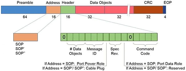 Figure 1: The PD message structure can dynamically go up to 356 bits in length. (Image source: Cypress Semiconductor, via embedded.com)
Power negotiation between PD devices
The USB PD 3.0 SPR defines several fixed voltage levels between 5 and 20 volts and only supports static power profiles up to 100 watts. Using the Programmable Power Supply (PPS) extension, a USB sink device can request in real-time a voltage from the USB power source between 3 and 21 volts in increments of 20 millivolts (mV), according to its needs.
The PPS thereby simplifies the switching converter electronics in the mobile device, reduces heat dissipation, and accelerates charging by optimizing power matching. USB PD 3.1 defines an extended power range (EPR) up to a maximum of 240 watts and uses an adjustable voltage supply (AVS) to regulate the bus voltage in a higher range between 15 and 48 volts.
Since 3 A already exceeds the current-carrying capacity of ordinary USB cables, the USB Implementers Forum (USB-IF) stipulates that special EMCA cables be used. These feature thicker wire cross-sections and cable insulation. The E-Marker chips in the cable plugs confirm these reinforced cable features using the PD protocol. In doing so, they influence the power negotiation between the source and sink device.
PD communication uses special K-codes to delineate messages. The special K-code sequence that indicates the start of a sequence is called the Start Of Packet (SOP). Three sequences are defined: SOP, SOP', and SOP'', so that a DFP (a power source such as a PD network charging adapter) can communicate as an initiator with either of the two E-Marker chips in the EMCA cable connectors, as well as with the UFP (USB power sink).
The flowchart in Figure 2 shows the message exchange during a successful power negotiation between two PD devices connected via an EMCA cable.
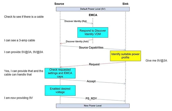 Figure 2: Shown is the successful power negotiation between two USB PD devices over an EMCA cable. Note: Rqt = Request; Ack = Acknowledge. (Image source: Cypress Semiconductor, via embedded.com)
Configure instead of program
The complexity of the PD protocol translates to a painstaking programming exercise for the developer. A faster approach is to instead configure a pre-programmed USB PD controller with custom features. An example controller is onsemi’s FUSB15101MNTWG. This is a highly integrated USB PD 3.1 controller that can control the primary-side switching regulator of an AC/DC adapter via an optocoupler, or directly control a DC/DC port current regulator.
This all-in-one solution minimizes circuit complexity through optimized hardware peripherals, including digital-to-analog and analog-to-digital converters, NTC temperature sensing, and NMOS gate drivers. Open-source firmware with an application programming interface (API) and the Eclipse-based integrated development environment (IDE) facilitate programming.
The FUSB15101 integrates a high-efficiency Arm® Cortex® M0+ processor with a UART interface and supports the PPS specification, regulating the output voltage from 3.3 to 21 volts. It offers programmable constant voltage (CV) and constant current (CC) regulation and compensates for cable losses. Also available are overvoltage, undervoltage, overcurrent, and over-temperature protection functions, as well as overvoltage protection diodes on the USB-C connector pins. The PD controller supports VCONN power for the E-Marker chips in EMCA cables, while its idle and sleep modes meet Certificate of Conformity (CoC) and Design of Experiments (DOE) requirements.
Typical applications include:
- USB PD compliant AC/DC adapter (see Application 1)
- USB PD compliant DC/DC ports (see Application 2)
Application 1: AC/DC switching power supply featuring USB PD output
In this application, the FUSB15101 USB PD controller controls the NCP1345Q02D1R2G quasi-resonant (QR) flyback switching regulator on the primary side of an AC/DC switching power supply via an optocoupler. The NCP1345 operates off of 9 to 38 volts from an auxiliary winding of the transformer while using a second auxiliary winding to generate a voltage that is four times higher in order to provide enough switching voltage for a MOSFET at low USB output voltages of 3.3 volts. On the secondary side, the NCP4307AASNT1G controller controls the synchronous rectification. Combining the three ICs results in a gear-shifting power supply that consistently achieves around 90% efficiency across the different PD power profiles.
Figure 3 shows the main circuit diagram of a USB-C PD 3.0 PPS mains charger based on the three ICs that deliver 65 watts (20 volts/3.25 A).
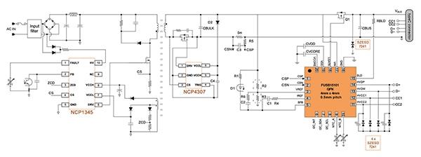 Figure 3: In this solution for USB PD wall chargers, the FUSB15101 controls the NCP1345 QR flyback switching regulator on the primary side of the AC/DC switching power supply via an optocoupler. (Image source: onsemi)
Programmers start their own USB PD power supply application by using onsemi's NCP1342PD65WGEVB evaluation board, shown in Figure 4.
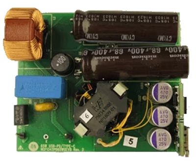 Figure 4: Using the NCP1342PD65WGEVB USB-C PD 3.0 wall charger evaluation board, programmers can get started right away. (Image source: onsemi)
The storage choke of this board, in the form of a compact RM8 transformer, provides 60 watts (20 volts/3 A) of output power. The NCP1342BMDCDD1R2G quasi-resonant flyback switching regulator operates off of 9 to 28 volts from only one auxiliary winding. Suitable for developing high-performance offline power converters and USB PD adapters, it features rapid frequency foldback (RFF) for improved efficiency across the load range. An integrated active X2 discharge capacitor eliminates the need for discharge resistors and enables power consumption below 40 milliwatts (mW) at no load.
Application 2: DC/DC current controller for a USB PD port
In this application, the FUSB15101 USB PD controller drives the NCV81599MWTXG four-stage buck/boost, step-up/down DC/DC converter controller. This allows a USB-C port that is otherwise limited to 15 watts to be expanded to a PD power source that provides more than 60 watts and is supplied by the device's internal DC power supply or a battery (Figure 5).
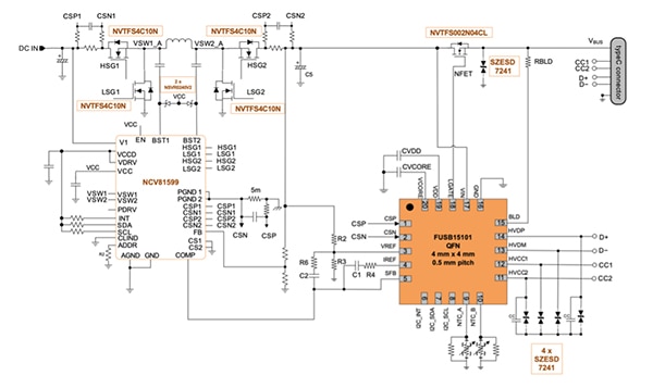 Figure 5: In this DC/DC port current controller application, the FUSB15101 controls the four-stage DC/DC converter controller NCV81599 directly. (Image source: onsemi)
Developers can save time and start testing and programming immediately with the NCV81599 by using the FUSB3307MPX-PPS-GEVB evaluation board. This DC/DC current regulator circuit converts a USB port into a PD 3.0 PPS current source, which delivers up to 5 A at bus voltages from 3.3 to 21 volts (Figure 6). The circuit is capable of detecting E-Marker cables and can be operated standalone or connected to test equipment.
 Figure 6: The FUSB3307MPX-PPS-GEVB is an evaluation board for the NCV81599 that turns USB ports into a PD 3.0 PPS power source. (Image source: onsemi)
A DC power supply or a battery supplies the VBAT input of the FUSB3307 board with 4.5 to 32 volts. The circuit handles constant voltage (CV) or constant current (CC) regulation and has protection against overvoltage, undervoltage, short-circuit, over-temperature, and cable-fault conditions.
Programming the FUSB15101
The FUSB15010 firmware is a highly optimized Type-C PD controller driver that supports the integrated Arm Cortex M0+ processor. The firmware has the flexibility to handle new PD messages as well as additional Type-C status flows. The code is organized in a modular fashion, separating the application source code, hardware abstraction layer, platform-dependent code, and USB Type-C PD core functions.
The PD core functions are configurable via project build options or by modifying the vendor info file “vif_info.h”. The code base includes an Eclipse sample project that can be compiled using the IDE, enabling faster startup for evaluating the Type-C PD standalone controller.
Table 1 summarizes the PD profiles supported by the FUSB15101; PDO is the power delivery object.
|
Table 1: Shown are the PD profiles supported by the FUSB15101. (Table source: onsemi)
As mentioned, the parameters of a charging profile can be modified very easily in the file “vif_info.h”. The following code shows how to change the maximum current in PDO 4 from 20 volts/3 A to 20 volts/3.25 A:
Current PDO values:
#define PORT_A_SRC_PDO_VOLTAGE_4 400 // 20000 mV
#define PORT_A_SRC_PDO_MAX_CURRENT_4 300 // 3.00 A
New PDO values:
#define PORT_A_SRC_PDO_VOLTAGE_4 400 // 20000 mV
#define PORT_A_SRC_PDO_MAX_CURRENT_4 325 // 3.25 A
Further details and instructions for installing the IDE, as well as firmware import and compiling the binary file, can be found in the FUSB15101EVBSPG guide.
The installation of the programming tools and the procedure of the one-time flash are described in the UM70086-D user manual. A suitable Arm Cortex-M programming and debug adapter to facilitate development is the 8.08.91 J-LINK EDU MINI from Segger Microcontroller Systems.
Checking the PD communication
To verify communication between two USB PD devices, developers can use Infineon Technologies' CY4500 protocol analyzer, which supports USB PD 3.0 and USB-C specifications. It performs non-intrusive testing and captures accurate protocol messages on the CC lines. The associated EZ-PD analysis software lists all the messages of a dialog between two USB PD devices and an EMCA cable in detail (Figure 7).
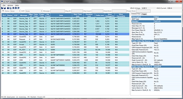 Figure 7: The EZ-PD analysis software tracks the dialog between two USB PD devices over the CC lines. (Image source: Infineon Technologies)
Conclusion
While it’s important to understand the basics of the USB PD protocol in order to adapt designs to meet the rising power needs of end-user devices, it is a complex protocol that can require extensive programming. To save time, developers can use pre-programmed, highly integrated USB PD controllers to boost 15 watt USB-C power to over 100 watts. AC/DC USB chargers, as well as DC/DC USB ports, can be enhanced with custom PD functionality by simply configuring the PD controller. Utilizing evaluation boards and a PD protocol analyzer facilitates the development process.

Disclaimer: The opinions, beliefs, and viewpoints expressed by the various authors and/or forum participants on this website do not necessarily reflect the opinions, beliefs, and viewpoints of DigiKey or official policies of DigiKey.


