How to Integrate GaN Power Stages for Efficient Battery-Powered BLDC Motor Propulsion Systems
2023-02-22
Battery-powered applications such as collaborative robots (cobots), electric bicycles, industrial drones, and power tools require lightweight and powerful electric motors with a small form factor. Brushless DC (BLDC) motors are a good option, but the motor drive electronics are quite complex with many design considerations. The designer must tightly regulate torque, speed, and position, while also ensuring high precision with minimal vibration, noise, and electromagnetic radiation (EMR). Additionally, bulky heatsinks and external wiring harnesses must be avoided to save weight, space, and cost.
As is often the case, the challenge for designers becomes one of balancing design requirements with time and budget pressures—while avoiding costly development errors. One way to do this is to take advantage of fast, low-loss semiconductor technologies such as gallium nitride (GaN) for the power stages required to drive the BLDC motors.
This article discusses the relative advantages of GaN-based power stages and introduces a sample device from EPC, implemented in a half-bridge topology. It explains how to use associated development kits to quickly get started on a project. In the process, designers will learn how to measure the parameters of a BLDC motor and operate it in sensorless field orientation control (FOC) with minimal programming effort using Microchip Technology’s motorBench Development Suite.
The advantages of GaN
To efficiently control a BLDC motor in battery applications, developers need an efficient, lightweight driver stage with a small form factor that can be implemented as close as possible to the actuator. For example, inside the motor housing.
Insulated-gate bipolar transistors (IGBTs) are robust and can switch high power up to 100 megawatts (MW) at a maximum of 200 kilohertz (kHz), but are not suitable for devices that have to manage battery charge at voltages up to 80 volts. The high contact resistance, free-wheeling diode, and switching losses, as well as the current tail during turn-off, all combine to result in signal distortion, excess heat generation, and spurious emissions.
Metal oxide semiconductor field-effect transistors (MOSFETs) switch faster and have lower switching and ohmic losses compared to IGBTs, but their gate capacitance requires a powerful gate driver to operate at high switching frequencies. Being able to operate at high frequencies is important as it means designers can use smaller electronic components to reduce overall space requirements.
Turning to GaN high-electron-mobility transistors (HEMTs), their high carrier mobility allows them to build up and breakdown semiconductor junctions extremely fast and with low losses. An integrated GaN driver, such as EPC's EPC23102ENGRT, features exceptionally low switching losses and high switching frequencies, enabling compact device designs in the tightest of spaces. The monolithic chip contains an input logic interface with level shifters, bootstrap loading, and gate driver circuits that control the GaN output FETs in a half-bridge topology (Figure 1). The chip package is optimized for high heat dissipation and low parasitic inductance.
") Figure 1: The EPC23102 contains control logic, level shifters, gate drivers, and GaN output FETs in a half-bridge topology (left). The chip package (right) is optimized for high heat dissipation and low parasitic inductance. (Image source: EPC)
Figure 1: The EPC23102 contains control logic, level shifters, gate drivers, and GaN output FETs in a half-bridge topology (left). The chip package (right) is optimized for high heat dissipation and low parasitic inductance. (Image source: EPC)
Less waste heat and lower EMR
The EPC23102 output transistors have a typical drain-source on-resistance (RDS(on)) of 5.2 milliohms (mΩ) (at 25°C). They handle voltages up to 100 volts and currents up to a maximum of 35 amperes (A). In addition, the lateral structure of the GaN device and the absence of an intrinsic body diode provide exceptionally low gate charge (QG) and reverse recovery charge (QRR).
Compared to a MOSFET device with a similar RDS(on), the GaN driver achieves up to five times lower switching losses. This allows a GaN-based inverter to operate at relatively high pulse width modulation (PWM) frequencies—up to 3 megahertz (MHz)—and with shorter dead time (below 50 nanoseconds (ns)).
High switching speeds (dV/dt) and the low temperature coefficient of GaN semiconductors in a package design with reduced parasitic inductance minimizes signal distortion, and thus minimizes EMR and switching losses. This reduces the need for filtering strategies, while the smaller low-cost capacitors and inductors save board space.
Along with low contact resistance RDS(on), the GaN device’s other advantages, such as the high thermal conductivity of the GaN substrate and the large thermal contact area of the component package, all combine to allow GaN power stages to switch currents up to 15 amperes (A) without a heatsink (Figure 2).
") Figure 2: Temperature rise versus phase current for a GaN power stage with an ambient temperature of 25.5°C and at different PWM frequencies. (Image source: EPC)
Figure 2: Temperature rise versus phase current for a GaN power stage with an ambient temperature of 25.5°C and at different PWM frequencies. (Image source: EPC)
The EPC23102 also features robust level converters from the low-side to the high-side channels that are designed to operate under soft and hard switching conditions—even at large negative terminal voltages—and to avoid false triggering by fast dV/dt transients, including those originating from external sources or adjacent phases. Internal circuitry integrates logic and bootstrap power charge and disable functions. Protection functions prevent unwanted turn-on of output FETs when supply voltages are too low—or even fail.
A ready-to-use motor inverter evaluation set
The easiest and fastest way to commission a three-phase BLDC motor with GaN technology is to use EPC’s EPC9176KIT motor inverter evaluation kit. It consists of the EPC9176 motor inverter board and a DSP controller board. A simple EPC9147E controller plug-in adapter for control via a customer-specific host controller is also included. The coupling connector carries the following signals: 3 × PWM, 2 × encoder, 3 × Uphase, 3 × Iphase, UDC, IDC, and 2 × status LED.
As a reference design, the EPC9176 motor inverter board facilitates in-house circuit design, while the EPC9147A controller board, when used with Microchip Technology's motorBench development environment, allows users to quickly get up and running without having to spend time coding or programming.
The three-phase BLDC motor inverter integrates three EPC23102 GaN half-bridge drivers to control AC or DC motors and DC/DC power converters. With an RDS(on) of 6.6 mΩ maximum, the power stage causes little heat loss at load currents up to 28 A peak (Apk) or 20 A rms (ARMS) in constant operation at switching voltages up to 100 volts. Configured for multiphase DC/DC conversion, the EPC23102 supports PWM switching frequencies up to 500 kHz and up to 250 kHz for motor drive applications.
The 8.1 × 7.5 centimeter (cm) EPC9176 motor inverter board contains all the critical functional circuitry necessary to support a complete motor inverter, including DC bus capacitors, gate drivers, regulated auxiliary voltages, phase voltage, phase current, and temperature measurement, along with protection functions and optional harmonic or EMR filters for each phase (Figure 3).
") Figure 3: The EPC9176 motor inverter features DC bus capacitors, gate drivers, a voltage regulator, voltage sensing, current and temperature protection functions, and EMR filters. (Image source: EPC)
Figure 3: The EPC9176 motor inverter features DC bus capacitors, gate drivers, a voltage regulator, voltage sensing, current and temperature protection functions, and EMR filters. (Image source: EPC)
The three-phase GaN inverter operates at input voltages from 14 to 65 VDC. It switches without overshoot, resulting in smooth torque and minimal running noise. The board is optimized for a GaN-typical high-speed switching slope below 10 volts per ns (V/ns) and can optionally be reduced to operate a DC/DC converter. Additionally, two rotor position sensors (Hall sensors) operating at different voltage levels can be connected.
Vibration-free torque and low running noise
An example of a three-phase BLDC motor implementation demonstrates the effect of dead-time parameterization on the smooth running of the motor, and thus, noise generation. The locking time at the switching transition of the high-side and low-side FET of a half-bridge based on GaN FETs can be chosen to be very small because the GaN HEMTs react extremely fast and do not produce parasitic overshoots, as is the case with the slower MOSFETs.
Figure 4 (left) shows a GaN inverter operating at a typical dead time for MOSFETs of 500 ns at a PWM frequency of 40 kHz. What should be a smooth sinusoidal phase current shows extremely high distortion, which results in high torque ripples and corresponding noise. In Figure 4 (right) the dead time was reduced to 50 ns, establishing a sinusoidal phase current for a smooth-running motor with very little noise.
") Figure 4: A dead time of 500 ns at a 40 kHz PWM frequency (left), typical for MOSFETs, causes high distortion in the phase current that results in high torque ripples and high noise levels. With a dead time of 50 ns (right), a sinusoidal phase current is established so that the motor rotates smoothly with low noise. (Image source: EPC)
Figure 4: A dead time of 500 ns at a 40 kHz PWM frequency (left), typical for MOSFETs, causes high distortion in the phase current that results in high torque ripples and high noise levels. With a dead time of 50 ns (right), a sinusoidal phase current is established so that the motor rotates smoothly with low noise. (Image source: EPC)
Less ripple in the phase current also means lower magnetization losses in the stator coils, while less ripple in the phase voltage allows higher resolution, as well as more precise control of torque and speed, especially for motors with low inductance used in smaller designs.
For motor drive applications that require more power, two GaN inverter boards are available: the EPC9167HCKIT (1 kilowatt (kW)) and the EPC9167KIT (500 watts). Both use the EPC2065 GaN FET, which has a 3.6 mΩ maximum RDS(on) and an 80 volt maximum device voltage. While the EPC9167 board uses single FETs for each switching position, the EPC9167HC has two FETs working in parallel, providing a maximum of 42 Apk (30 ARMS) output current. The EPC2065 GaN FET supports PWM switching frequencies up to 250 kHz in motor control applications and a maximum of 500 kHz in DC/DC converters.
Even higher power—up to 1.5 kW—is provided by the inverter board in the EPC9173KIT. The board forms the half-bridge branches of two single EPC23101ENGRT GaN gate driver ICs that have only one integrated high-side power FET. This board can be expanded as a buck, boost, half-bridge, full-bridge, or LLC converter. It delivers output currents up to 50 Apk (35 ARMS) and operates at PWM switching frequencies up to 250 kHz, with appropriate cooling.
Get the driver stage up and running in a few minutes
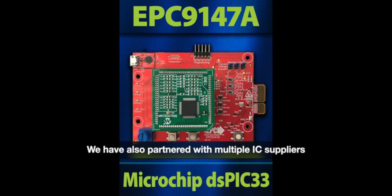
The fastest way to evaluate the EPC9176 GaN inverter board—without having to code—is to use the EPC9147A controller interface board. A plug-in module (PIM)—the MA330031-2—contains the dsPIC33EP256MC506-I-PT 16-bit DSP from Microchip Technology (Figure 5).
") Figure 5: The EPC9147A universal controller interface card can accommodate various plug-in modules, such as the MA330031-2 PIM, which is based on the 16-bit dsPIC33EP256 DSP. (Image source: EPC/Microchip Technology)
Figure 5: The EPC9147A universal controller interface card can accommodate various plug-in modules, such as the MA330031-2 PIM, which is based on the 16-bit dsPIC33EP256 DSP. (Image source: EPC/Microchip Technology)
To facilitate the operation of the DSP controller interface, designers can use the motorBench Development Suite, to which they must add:
- MPLAB X IDE_V5.45 and the recommended update
- Code Configurator Plugin (DSP specific compilation)
- motorBench plugin 2.35 (motor examples)
For this discussion, the example uses the EPC9146 GaN motor inverter board, so:
- Start with MCLV-2 or EPC project for the EPC914xKIT named, “sample-mb-33ep256mc506-mclv2.X”
The user can simply select the sample hex file for the EPC9146 GaN motor inverter board and flash it into the DSP dsPIC33EP256MC506 using a programming adapter, such as Microchip Technology's PG164100 for 16-bit microcontrollers. The connected BLDC motor (Teknic_M-3411P-LN-08D) is then manually controllable via the controls and operates in sensorless FOC mode.
If the motor is not running satisfactorily or needs to be configured for a different operating state, motorBench also provides a configurable sample file that must be compiled prior to flashing. An elementary but important parameter for GaN motor drivers, as discussed above, is a dead time of 50 ns or smaller, which must absolutely be checked before compiling the hex file.
Custom parameters for a BLDC motor
In order to configure custom BLDC motor configurations for sensorless FOC operation using the motorBench IDE, users can measure their specific motor parameters and enter the relevant values in a configuration file. The MOT-I-81542-A motor from ISL Products International, for example, can serve as a test motor here. It consumes about 361 watts of power operating off 24 volts and running at 6100 revolutions per minute (rpm).
These four motor parameters must first be determined:
- Ohmic resistance: This is measured between the stator coil terminals using a multimeter
- Inductance: Measured between the stator coil terminals using a multimeter
- Pole pairs: To determine the pole pairs, the designer must short-circuit two phases, leave the third open, and then count the number of latches at one shaft revolution by hand, then divide the result by two
- Back electromotive force (BEMF): BEMF is measured between the stator coil terminals using an oscilloscope. To do so, the designer must:
- Clamp the probe to two phase leads, leaving the third open
- Rotate the motor shaft by hand and record the voltage response
- Measure peak-to-peak voltage App and period Thalf of the largest sine half-wave (Figure 6).
") Figure 6: The BEMF is determined by measuring peak-to-peak voltage App and period Thalf of the largest sine half-wave. (Image source: EPC)
Figure 6: The BEMF is determined by measuring peak-to-peak voltage App and period Thalf of the largest sine half-wave. (Image source: EPC)
Referring to the above project example, Microchip determined the following parameters for the Teknic M-3411P-LN-08D motor (8.4 ARMS, eight poles, torque = 1 Newton-meter (Nm), and a power rating of 244 watts):
- App = 15.836 Vpp
- Thalf = 13.92 ms
- Pole pairs: pp = 4
- Microchip then calculated the BEMF constant (for 1000 rpm = 1 krpm), using Equation 1:
") Equation 1
Equation 1
 for this example motor
(a value of 10.2 was used for motorBench)
- RL-L = 800 mΩ line-to-line resistance, minus 100 mΩ due to LCR meter leads
- Ld = Lq = 1 mH used in this example, despite measuring 932 microhenries (µH)
The determined parameters are entered into the motorBench submenu Configure/PMSM Motor. To do this, designers can simply use the XML configuration file of a similar motor type. Alternatively, the parameters can be entered into a newly created (empty) configuration file that can be imported via the "Import Motor" button.
Conclusion
GaN motor driver ICs achieve high-efficiency performance in battery-powered BLDC motor drives with a small form factor and low weight. Integrated into the motor housing, they are well-protected, simplify device design and installation, and reduce maintenance.
Supported by reference circuits, pre-programmed model-based DSP controllers, and a motor development environment, designers and programmers of BLDC motor applications can shorten circuit design time and focus more on application development.
Disclaimer: The opinions, beliefs, and viewpoints expressed by the various authors and/or forum participants on this website do not necessarily reflect the opinions, beliefs, and viewpoints of DigiKey or official policies of DigiKey.