How to Implement LoRa Firmware Over the Air (FOTA) with Minimal Power Consumption
Contributed By DigiKey's North American Editors
2019-02-13
In October 2018 the LoRa Alliance announced specifications that standardized firmware over the air (FOTA) updates for IoT endpoints. While this is good news for LoRa networks, it presents a challenge to designers of low-power IoT LoRa endpoints using flash microcontrollers.
Compared to reading, writing to microcontroller flash memory temporarily but dramatically increases the microcontroller’s power consumption. It also requires the use of a larger voltage regulator to handle the increased power.
Neither of these are desirable, but this article will describe how the use of a microcontroller with FRAM can be used as a low-power way to write firmware. Paired with a new LoRa transceiver, the combination forms a lower power solution for FOTA compared to the traditional flash microcontroller approach.
What is LoRa?
With the Internet of Things (IoT), one of the goals is to transmit data wirelessly using as little power as possible. Designers of battery-powered sensor applications have been especially concerned with wirelessly sending low rate sensor data over many miles while minimizing battery power use. Of the existing solutions, Bluetooth and Zigbee are designed for short-range applications, and cellular data is relatively power heavy. LoRa has emerged as one popular solution to this problem.
LoRa is shorthand for long range. LoRa wireless networking was developed for low data rate, low-power, long range transmission of non-real-time data. The data rate is between 0.3 kilobits/second (kbits/s) and 5.5 kbits/s, making it appropriate for periodic sensor data transfers. While LoRa specifications describe the modulation and electrical characteristics of the network, LoRaWAN (wide area network) describes the protocols and data format of a LoRa network.
LoRa signaling is similar to FM in that it modulates a signal by changing its frequency. However, while a properly modulated FM signal changes frequency instantaneously, a LoRa modulated signal slowly increases or decreases frequency over a period of time. This gradual increase or decrease in frequency is called a chirp, and the method is called chirp modulation. The rate of frequency change over time is called “chirpiness”.
LoRaWAN networks are always arranged in a star topology, and the signaling and access protocol is designed to use minimal power and minimize signal collisions for multiple endpoints. Each LoRaWAN endpoint sends its data to a gateway which transfers the data to another network such as Ethernet or Wi-Fi. Typically, the gateway receives all the LoRaWAN data and transfers it over the network to a central computer for storage or further processing.
The range of any wireless communications is dependent upon the environment. In urban cities and towns, the expected LoRaWAN transmission distances can be from 1 to 3 miles. Rural country areas can see ranges of 3 to 9 miles, and direct line-of-sight data transmissions can reach up to 131 miles. In one case, a LoRaWAN endpoint in a weather balloon was able to transmit data to a gateway on the ground 436 miles away using only 25 milliwatts (mW) transmit power.
Each LoRa endpoint has three sections:
- One or more sensors to gather data
- A microcontroller
- A Semtech LoRa radio chip
The sensors are the reason for the endpoint. LoRa sensor applications can include temperature and humidity monitoring, fluid level monitoring of water and fuel, and air and liquid pressures. These types of sensors collect static data that does not change quickly over time, and therefore can be wirelessly transmitted at only 5.5 kbits/s with no impact on the application.
The radio chip and antenna directly communicate over the LoRa network. Semtech is the company that owns the patents on the LoRa transmission scheme. Presently, all LoRa radios either use Semtech radio chips or use radio modules that have Semtech radio chips inside them.
The Semtech SX1262IMLTRT LoRa radio transceiver is designed for battery-powered LoRa applications and complies with the LoRaWAN radio transmission standard (Figure 1). When transmitting or receiving data, it draws only 4.2 milliamperes (mA) with an RF output power of +22 dBm. A lower power version, the SX1261, has an RF output power of +15 dBm. Both are half-duplex transceivers that operate in the sub-GHz range and handle constant envelope modulation schemes such as LoRa, as well as frequency shift keying (FSK). Both DC-DC buck converter and linear LDO regulation are provided on board.

Figure 1: The Semtech SX1262IMLTRT and SX1261 are self-contained half-duplex radios for LoRa applications that include both a DC-DC buck converter and linear LDO regulation on board. (Image source: Semtech)
Selecting a microcontroller for a LoRaWAN endpoint
The microcontroller in a LoRaWAN endpoint reads and processes the sensor data, and also interfaces to the SX1262 to transmit the data over the network. The microcontroller must have enough memory for the SX1262 drivers, sensor drivers, and application code. Requirements for a microcontroller in a LoRaWAN endpoint using the Semtech SX1262 radio chip are shown in Table 1.
|
Table 1: The minimum requirements for a microcontroller are shown for a simple LoRaWAN endpoint that collects and transmits sensor data with minimal processing. For more complex endpoints, the recommended requirements provide a more robust system. (Table source: Semtech)
Per the Table, the minimum requirements for a basic standalone LoRaWAN endpoint can be implemented on an 8-bit microcontroller. This can be a simple, low-power LoRaWAN endpoint that only needs to occasionally transmit raw sensor data back to a gateway.
However, if the endpoint handles a lot of traffic or must perform some processing on sensor data, the recommended requirements in Table 1 should be followed. Of course, as memory and processing power increases in a LoRaWAN endpoint, the power consumption of the endpoint increases, requiring a battery with more capacity. This is contradictory to the design intention of LoRaWAN for low-power IoT endpoints.
When designing a LoRaWAN endpoint it is important to stay focused on the fact that it is a low-power system, and not allow feature creep to complicate the system and end up drawing more power than necessary. When selecting a microcontroller for a LoRaWAN endpoint, an eye should be kept on keeping clock speed and memory size as low as possible, as these also affect power consumption.
Updating microcontroller firmware in a LoRaWAN endpoint
In October of 2018, the LoRa Alliance standardized how firmware updates over the air (FUOTA) for LoRa endpoints are performed for all LoRa networks. The new standards provide for network-wide clock synchronization, which dramatically reduces the number of lost data packets. It also standardizes multicast transmissions which is necessary when transmitting the same firmware update to multiple endpoints. Both clock synchronization and multicast transmissions require an accurate timebase, which means all LoRa endpoints must have microcontrollers that have an RTC accurate down to one millisecond.
While updating firmware in LoRaWAN endpoints is an important function, it brings a new problem. Updating firmware in the field means reprogramming the microcontroller’s program memory, which is typically non-volatile flash memory. Programming flash memory requires the application of 10 volts or more to the memory cell. This requires a larger voltage regulator and related circuitry just to program the flash memory. As firmware updates in some networked systems may occur only a few times a year, this is an investment that raises cost and uses extra board space inefficiently.
There is an alternative to a microcontroller with flash memory, a microcontroller with ferroelectric random access memory (FRAM). FRAM memory needs only 1.5 volts to program a cell. A good example that meets the recommended requirements for a LoRaWAN node is the 16-bit MSP430FR6047 FRAM-based microcontroller from Texas Instruments. This has 256 Kbytes of FRAM program memory and an RTC with calendar and alarm functions. An encryption block supports AES-128 and AES-256. It supports up to four SPI ports and has more than enough external interrupt inputs to support the four needed by the Semtech SX1262, making interfacing the two devices very easy. Also, IEEE 64-bit extended unique identifier (EUI) generation can be easily implemented in firmware (Figure 2).
Figure 2: The MSP430FR6047 has 256 Kbytes of FRAM, 8 Kbytes of SRAM, and a wide range of peripherals for sensor-based applications. (Image source: Texas Instruments)
The MSP430FR6047 is designed for battery-powered smart meters and has an integrated ultrasonic sensing peripheral which provides highly accurate detection of water flow and liquid level sensing. These advanced features are easily adapted for many different sensor applications.
While the MSP430FR6047 only has 8 Kbytes of RAM instead of the recommended 16 Kbytes, this may not be an issue in a LoRaWAN sensor endpoint if complex sensor fusion processing is not required. Also, the MSP430FR6047 has a high degree of integration that improves performance while saving memory and board space. An analog front-end for ultrasonic sensing applications includes a programmable pulse generator, a 12-bit analog-to-digital converter (ADC), and a programmable gain amplifier, all very useful when collecting data from analog sensors.
The MSP430FR6047 has a 32-bit hardware multiplier, and a low energy accelerator (LEA) signal processing core capable of performing 256 point FFT computations independent of the MSP430 core. The LEA accelerates signal processing for low-power applications, extending battery life.
The MSP430FR6047 is extremely low power, even in the context of 8-bit and 16-bit microcontrollers, which already are low-power devices. With the MSP430 16-bit core and peripherals running it draws only 120 microamperes per megahertz (µA/MHz). Standby mode with the RTC running draws only 450 nanoamperes (nA). The microcontroller does have a shutdown mode that only draws 30 nA, but that also turns off the real time clock (RTC) so shutdown mode is not recommended for a LoRaWAN endpoint.
Designing with FRAM for FUOTA
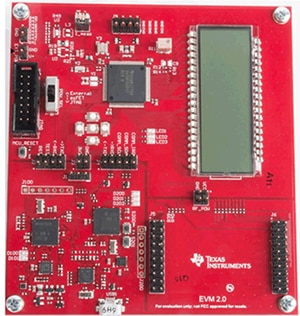
For MSP430FR6047 firmware development, the EVM430-FR6047 evaluation board is available. It is USB powered and contains all the hardware necessary to evaluate the MSP430 in an application. The evaluation board has connectors for BoosterPack™ modules to add additional functionality to the board. Additional pins are available on the board for connecting sensors.

Figure 3: The Texas Instruments EVM430-FR6047 evaluation board for the MSP430FR6047 has an LCD display and provides access to all pins on the MSP430FR6047. (Image source: Texas Instruments)
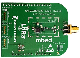
For evaluation and development of the SX1262, Semtech provides the SX1262MB2CAS LoRa MBED shield (Figure 4).

Figure 4: The Semtech MBED shield for the SX1262 is a simple evaluation board containing the SX1262 RF transceiver. (Image source: Semtech)
The MSP430 BoosterPack connectors provide all the necessary signals needed to interface the MSP430 to the Semtech SX1262 MBED shield. The BoosterPack connector has the necessary four SPI pins, as well as three extra GPIO pins that can be configured either as polled inputs to the MSP430, or configured as external interrupts. If an additional external interrupt is needed, four of the pins on the BoosterPack connector are connected to one of the MSP430 UARTs. These UART pins can be configured either as GPIO or external interrupts for the MBED shield. Although the BoosterPack and MBED shield are not physically pin compatible, they can be easily jumpered to provide the necessary connections between the MSP430 and the SX1262.
Additionally, Texas Instruments provides Code Composer Studio™, an IDE that supports writing and debugging MSP430 code.
Conclusion
LoRa has emerged as a popular standard for transmitting IoT sensor data. The standard has been extended to include FUOTA, bringing with it new challenges to long battery life. By opting for FRAM-based microcontrollers instead of flash memory, designers can greatly reduce the power required to write these updates to device memory.
Also, as shown, the choice of microcontrollers becomes even more important to minimize battery drain, while providing enough processing power for the application.

Disclaimer: The opinions, beliefs, and viewpoints expressed by the various authors and/or forum participants on this website do not necessarily reflect the opinions, beliefs, and viewpoints of DigiKey or official policies of DigiKey.


