How to Use Ultrasonic Sensing in Smart Water Meters
Contributed By DigiKey's North American Editors
2022-12-06
Expanding and improving smart water metering is an essential element in effective water management. Metering helps identify and locate leaks in water distribution systems and can help users improve water conservation during drought or other water supply limitations. Ultrasonic flow meter technology is gaining adoption in industrial, commercial, and residential settings. These meters offer several benefits compared with traditional mechanical water meters: there are no moving parts, minimizing maintenance and maximizing reliability, they are low power and a battery can last for many years, they provide high accuracy, and they can be designed to support bi-directional measurements.
This article describes the operation and integration of ultrasonic flow sensors in smart water meters and briefly reviews the international standards for residential meter accuracy. It then presents examples of components suitable for use in those meters, including an ultrasonic sensor assembly from Audiowell, analog front end (AFE), and time-to-digital converter (TDC) ICs, plus a microcontroller unit (MCU) and evaluation board from Texas Instruments, as well as “support” components including an RF transceiver with secure boot from Silicon Labs, and a long-life primary battery from Tadiran. It concludes with some suggestions for improving ultrasonic flow meter accuracy.
A typical transit time ultrasonic flow meter includes two piezoelectric transducers to generate two series of ultrasonic pulses sent in opposite directions through the flowing water. The time of flight (ToF, or travel time) difference between the downstream and upstream pulses is used to measure the flow rate of the water. Other functional blocks include (Figure 1):
- An acoustic mirror for each of the piezoelectric transducers
- A transit ToF IC, this often consists of two ICs, an analog front end to interface with the transducers and a separate picosecond accurate stopwatch to measure the ToF
- A microcontroller to calculate the flow and link to the communications IC and an optional display
- A long-life battery or other power source (not shown)
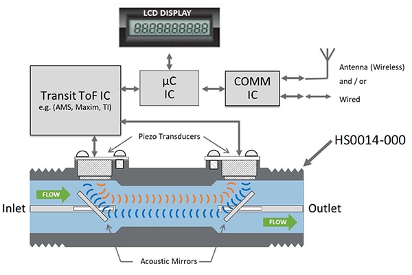 Figure 1: Two series of ultrasonic pulses are sent in opposite directions. The time of flight (travel time) difference between the downstream (blue) and upstream (red) pulses is used to measure the flow rate of the water. (Image source: Audiowell)
At the beginning of each ultrasonic pulse, a “start” signal is generated to mark the beginning of the ToF measurement. When the pulse reaches the receiver, a ‘stop’ signal is generated, and the interval between ‘start’ and ‘stop’ is used to determine the ToF based on a stopwatch function. When no water is flowing, the transit-time measurements will be identical. In normal flowing conditions, the upstream wave will travel slower than the downstream wave. If the water flows in the reverse direction, the wave travel speeds will be reversed with respect to the sensors.
Standards for residential meter accuracy
Flow meters intended for residential applications must be designed to meet various standards. For example, the metrological requirements for the maximum permissible error (MPE) for water meters are defined by the International Organization of Legal Metrology (OIML) by a series of values called Q1, Q2, Q3, and Q4 (Table 1).
|
Table 1: The OIML standards for residential water meters MPEs are based on a series of four flow-rate zones. (Table source: Texas Instruments)
The numerical value of Q3 designates a water meter in cubic meters per hour (m3/h) and the ratio Q3/Q1. The value of Q3 and the ratio of Q3/Q1 are found in lists included in the OIML standards. Water meters are defined as Class 1 or Class 2 based on MPEs:
- Class 1 meters
- MPE for the lower flow-rate zone, between Q1 and Q2, is ±3%, regardless of the temperature.
- MPE for the upper flow rate zone, between Q2 and Q4, is ±1%, for temperatures from 0.1 to +30°C, and ±2% for temperatures greater than +30°C.
- Class 2 meters
- MPE for the lower flow rate zone is ±5%, regardless of the temperature.
- MPE for the upper flow rate zone is ±2%, for temperatures from 0.1 to +30°C, and ±3% for temperatures greater than +30°C.
Ultrasonic cold water flow tube
The HS0014-000 ultrasonic flow sensor from Audiowell consists of a pair of ultrasonic flow transducers and corresponding reflectors in a DN15 polymer pipe that designers can use in ToF smart water meters (Figure 2). It features a low-pressure loss, high reliability, and ±2.5% accuracy. It’s rated for operation from 0.1 to +50°C and operates with a maximum input of 5 volts peak-to-peak at 1 MHz, and is designed for use in Class 2 residential applications as defined in the OIML standards.
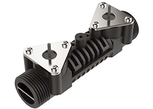 Figure 2: The HS0014-000 ultrasonic flow sensor includes a pair of ultrasonic flow transducers in a polymer pipe. (Image source: Audiowell)
Texas Instruments (TI) offers a trio of ICs that designers can use with the HS0014-000 in ultrasonic ToF water meters. The TDC1000 is a fully integrated AFE for ultrasonic sensing measurements. It’s programmable and can be set up for multiple transmit pulses, frequencies, signal threshold, and gain suitable for transducers operating from 31.25 kiloHertz (kHz) to 4 MegaHertz (MHz), with varying quality (Q) factors. The TDC1000 features low-power operating modes suitable for battery-powered smart ultrasonic ToF flow meter designs.
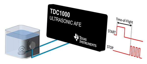 Figure 3: The TDC1000 is a fully integrated AFE can be paired with the HS0014-000 in ToF smart water meter designs. (Image source: Texas Instruments)
The second IC from TI is the TDC7200, a TDC and picosecond accurate stopwatch (Figure 4). This device has an internal self-calibrated time base that enables picosecond conversion accuracy and supports accurate measurements of low flow and no flow conditions. In addition, the autonomous multi-cycle averaging mode can be used to allow the host MCU to enter sleep mode to save power, with the MCU waking up only when the measurement sequence has been completed by the TDC7200.
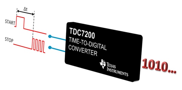 Figure 4: The TDC7200 TDC and picosecond-accurate stopwatch are designed to work with the TDC1000 AFE. (Image source: Texas Instruments)
TI also offers the MSP430FR6047, an ultra-low-power MCU with an integrated ultrasonic sensing analog front end for precise and accurate measurements. This device includes a low-energy accelerator for signal processing, enabling designers to optimize power consumption to extend battery life. The MSP430FR600x MCUs also integrate several peripherals useful for smart metering designs, including:
- LCD driver
- Real-time clock (RTC)
- 12-bit successive-approximation-register (SAR) analog-to-digital converter (ADC)
- Analog comparator
- Encryption accelerator for AES256
- A cyclic redundancy check (CRC) module
Ultrasonic meter EVB
To speed the development process and reduce time to market, designers can use the EVM430-FR6047 to evaluate the performance of the MSP430FR6047 MCUs for ultrasonic sensing in smart water meters (Figure 5). The EVM supports a variety of transducers ranging from 50 kHz to 2.5 MHz and includes an onboard LCD to display measurements and connectors for integrating RF communication modules.
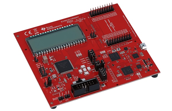 Figure 5: The EVM430-FR6047 can be used to evaluate the performance of the MSP430FR6047 in ultrasonic ToF sensing in water meters. (Image source: Texas Instruments)
Support components
The EFR32FG22C121F512GM32 EFR32FG22 Series 2 wireless SoCs from Silicon Laboratories is a single-die solution that combines a 38.4 MHz Cortex-M33 with a high-performance 2.4 GigaHertz (GHz) radio and integrated security features that provide fast encryption, secure boot loading and a debug access control (Figure 6). This device has up to 6 decibel meters (dBm) maximum power output and a receive sensitivity of -102.1 (250 kbit/s OQPSK) dBm. The EFR32FG22C121F512GM32 combines ultra-low transmit and receive power (8.2 milliamperes (mA) transmit at +6 dBm, 3.6 mA receive), 1.2 microampere (µA) deep-sleep mode power and provides a robust radio frequency (RF) link for reliable communications and high energy efficiency for smart meters and similar applications.
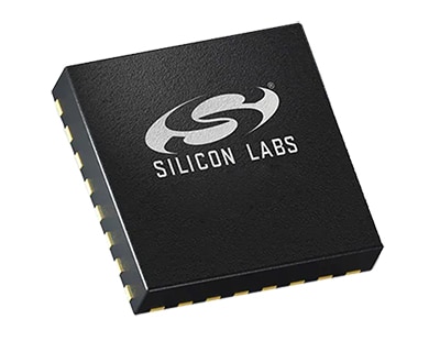 Figure 6: EFR32FG22 Series 2 wireless SoCs include a 38.4 MHz ARM Cortex-M33 core with fast encryption and secure boot-loading functions. (Image source: DigiKey)
Bobbin-type lithium thionyl chloride (LiSOCl2) batteries like the TL-5920/T with solder tabs (Figure 7) and TL-5920/S with standard connections from Tadiran are especially suited for use in water, gas, and electric smart meters. These primary batteries have a nominal capacity of 8.5 ampere hours (Ah) when discharged at a rate of 3 mA to a terminal voltage (V) of 2 V, a rated voltage of 3.6 V, maximum continuous current rating of 230 mA, maximum pulse current rating of 400 mA, and an operating temperature range of -55 to +85 °C. These batteries can last 20 to 30 years—as long as the meter—without needing expensive battery replacement.
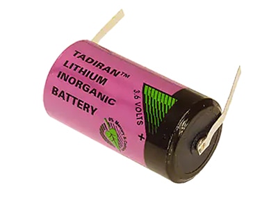 Figure 7: LiSOCl2 batteries like the TL-5920/T can last up to 30 years and are well suited for smart meter applications. (Image source: DigiKey)
Improving accuracy
Compensation, calibration, and impedance matching techniques can be used to improve the accuracy of ultrasonic ToF water meters:
- Measurement accuracy in ultrasonic ToF meters is limited by the degree to which the speed of sound is constant, as well as the accuracy of the signal processing electronics. The speed of sound can vary with density and temperature. Compensation should be added to calibrate and adjust for changes in the speed of sound and any variations in the signal processing circuitry.
-
Ultrasonic ToF meters are usually dry calibrated in the factory. Calibration parameters can include the time delays due to transducers, electronics, and cables, any needed ΔToF-offset correction for each acoustic path, and design-dependent geometrical parameters. Factory calibration can improve accuracy at low-flow and no-flow conditions and should not affect accuracy under high flow rate conditions.
- A highly symmetrical pair of transmit and receive signal paths are needed to minimize or eliminate ΔToF-offset under static flow conditions. An impedance matching solution can be used to control the impedances of each path. This simplifies ΔToF calibration and results in a very small drift of the error at zero flow over the operational pressure and temperature ranges, even if the transducers are not perfectly matched.
Summary
Ultrasonic ToF smart water meters are gaining market share in residential, industrial, and commercial applications to help identify and locate leaks in water distribution systems and provide users with the information needed to improve water conservation. Piezoelectric transducers are used to generate two series of ultrasonic pulses that are sent in opposite directions through the flowing water. The ToF difference between the downstream and upstream pulses is used to measure the flow rate of the water and can support bidirectional flow measurements. These meters have no moving parts making them highly reliable and energy efficient. The OIML has set international standards for classifying water meter MPE levels. Compensation techniques, calibration, and impedance matching can be used to improve the accuracy of these meters.

Disclaimer: The opinions, beliefs, and viewpoints expressed by the various authors and/or forum participants on this website do not necessarily reflect the opinions, beliefs, and viewpoints of DigiKey or official policies of DigiKey.


