How to Design for a Safer World Using Energy-Efficient Surveillance-Camera PTZ ICs
Contributed By DigiKey's North American Editors
2023-02-03
The use of video surveillance continues to spread, driven in part by developments in artificial intelligence (AI) as part of various “smart cities” initiatives with smart, automated surveillance of public streets, alleys, and gathering places. There is also increasing use of video surveillance in enclosed areas such as offices, retail shops, residential lobbies, supermarkets, museums, construction sites, industrial settings, and warehouses for safety and security. This widespread use, combined with the requirements of AI-based analysis, means designers are competing to improve system efficiency and performance while also lowering costs.
These improvements can, in large part, be accomplished using a combination of compact, low-power, sensitive, high-resolution imaging ICs combined with smart, precision, motion control systems. Using elements of this approach, designers can enable energy-efficient, remote video monitoring that can increasingly eliminate the need for someone to physically check an area or premises due to ambiguous images or incidents that are out of a camera’s line of sight.
As with any growing application area, however, there are a variety of technical challenges to be overcome, many of which can be addressed directly using energy-efficient electronic subsystems for camera pan, tilt, and zoom (PTZ).
This article looks at the role of PTZ in surveillance and discusses how energy-efficient, precision, low-power motor and motion control electronics for controlling PTZ functions are key to implementing video surveillance systems. It then introduces and studies the application of motion control ICs from TRINAMIC Motion Control GmbH, now part of Analog Devices, Inc. Evaluation boards are also described.
Effective surveillance enhanced with PTZ motion control
Whether for security installations or process monitoring, modern video surveillance systems are much more than just a camera pointed in a fixed orientation at a target zone. Instead, AI is making more efficient use of captured images by reducing false alarms and ensuring optimal deployment of resources, while the use of motorized PTZ allows the camera to scan left to right (pan) and move up and down (tilt), thus redefining the area being watched (Figure 1). Both AI and PTZ contribute to a more efficient and generally “greener” approach to surveillance. In the case of PTZ, and depending on the system design, the motion can be directed autonomously by the camera assembly, remotely controlled by a security system, or even manually operated.
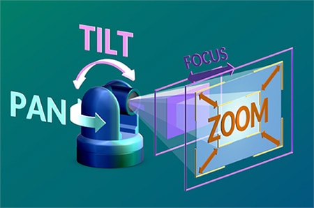 Figure 1: A surveillance camera with left-to-right pan, up-and-down tilt, and in/out zoom (PTZ) offers much more flexibility than a static fixed-in-place camera. (Image source: Aximmetry Technologies Ltd.)
This movement of the camera via pan and tilt overcomes the tradeoff dilemma of using a wide-angle lens and a wide field of view (FOV) that can capture a larger area, but at the expense of scene detail and with the introduction of curvature distortion. PTZ capability also provides cost savings for a security system, as one camera can do the job of many static cameras.
The motion of the camera can be directed via different techniques. Surveillance cameras with PTZ capability often also support multiple preset positions where the user can specify desired positions to monitor, along with the scheduled sequencing and timing of stepping from position to position. This provides remote surveillance of a wide area with no user input.
Matching electronics to PTZ motors
While motion control is at the heart of PTZ implementation, important factors in effective PTZ systems are smooth and accurate tracking via superior motor control. Designers can consider both brushless DC motors and the more challenging – but often advantageous – stepper motors for high precision and can achieve the necessary smoothness and accuracy using ADI’s Trinamic technology and ICs.
Low-power operation is also critical. Many of the surveillance cameras equipped with sophisticated PTZ control are now Power over Ethernet (PoE)-enabled devices. The latest PoE standard (IEEE 802.3bt-2018) supports up to 100 watts per Ethernet cable connection.
Designers of PTZ systems have three choices for the motor type, and the choice determines the control ICs to be used. The options are the classic brushed DC motor, the brushless DC (BLDC) motor, and the stepper motor (Figure 2).
 Figure 2: The three basic DC motors are the venerable brushed, brushless, and stepper motors. (Image source: Analog Devices)
Each motor arrangement has tradeoffs in capabilities, performance, and management/control needs:
The brushed DC motor was the first DC motor developed and has been in successful use for over 100 years. It is simple in design but difficult to control and works best for open-ended free-running situations rather than precise positioning or stop-and-go operation. Further, its brushes are subject to wear, have reliability issues, and can generate unacceptable electromagnetic interference (EMI). While it is still used in low-cost mass-market applications such as toys, and even some high-end applications such as medical infusion pumps, it is generally not a viable option for PTZ designs.
The BLDC motor (also called an electronically commutated, or EC, motor) is a good fit for closed-loop designs with a position sensor, which can also be used for velocity control (Figure 3). It can achieve high speeds and long life while packing high power density.
 Figure 3: The BLDC motor is most often used in a closed-loop arrangement for positioning precision and high speed; a shaft-mounted position sensor provides the needed feedback to the servo controller. (Image source: Analog Devices)
Control of BLDC motors requires precise timing of the current that energizes the motor’s stator coils. To enhance performance and precision, closed-loop feedback is often used. For this, an encoder can be used to sense rotor position, along with coil-current sensing for designs implementing field-oriented control (FOC) (more on FOC later).
The Trinamic TMC4671-LA multiphase servo controller/motor driver is an IC specifically designed for this task, and it is hardwired with an embedded FOC algorithm for BLDC motors (Figure 4).
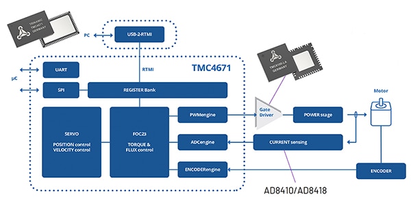 Figure 4: The Trinamic TMC4671-LA servo controller/motor driver, designed for BLDC motors, is hardwired with an embedded FOC algorithm. (Image source: Analog Devices)
It can also be used for other motor types, such as permanent magnet synchronous motors (PMSMs), as well as two-phase stepper motors, DC motors, and voice-coil actuators. Note that the difference between the BLDC motor and the PMSM is that the former is a direct current (DC) motor, while the PMSM is an alternating current (AC) motor. Thus, the BLDC motor is an electronically commutated DC motor that does not have a physical commutator assembly; in contrast, the PMSM is an AC synchronous motor that uses permanent magnets to provide the necessary field excitation.
The TMC4671-LA uses a basic SPI or UART interface to communicate with its microcontroller. It implements all needed control functions and features in hardware, along with error/fault-condition monitoring. It includes integrated analog-to-digital converters (ADCs), position-sensor interfaces, position interpolators, and other functions necessary to enable a complete controller for a wide range of servo applications.
This functionality is critical in order to meet the BLDC motor control challenge, as these algorithms are very sophisticated. Fortunately, complicated specifics are fully taken care of by the IC, so these details are not a burden to the design engineer or the system microcontroller (Figure 5).
 Figure 5: The TMC4671-LA contains and executes the multiple linked functional blocks needed for complex, precision BLDC control functions, such as FOC, thereby off-loading this task from the designer and the host processor. (Image source: Analog Devices)
Its 100 kilohertz (kHz) control-loop frequency, which is five times higher than the 20 kHz frequency of many BLDC controllers, yields critical benefits that include faster settling time, faster response to torque-control commands, better position stability, and reduced risk of overcurrent situations. The latter of which are potentially damaging to the motor driver or motor.
The stepper motor is an alternative to the BLDC motor. This motor is well-suited to open-loop positioning or velocity operation, as well as providing high torque at low and mid-range velocities (Figure 6). In general, stepper motors with comparable performance are less expensive than BLDC motors, but they have operating challenges that must be addressed.
 Figure 6: Compared to the BLDC motor controller, the stepper motor controller has a more direct path from the host to the motor drivers and the motor. (Image source: Analog Devices)
At first glance, the stepper motor controller signal-path flow appears to be somewhat simpler than the BLDC motor controller. While this is true in some ways, a precise and effective stepper motor controller must provide the specific functions to meet the needs of that motor.
ICs such as the TMC5130A, a high-performance controller and driver IC with serial communication interfaces—and which targets two-phase stepper motors—is designed to minimize or eliminate the associated issues (Figure 7).
 Figure 7: The TMC5130A is a high-performance controller and driver IC with serial communication interfaces targeting two-phase stepper motors. (Image source: Analog Devices)
This device combines a flexible ramp generator for automatic target positioning with a highly advanced stepper motor driver. It also includes internal MOSFETs that can directly deliver up to 2 amperes (A) of coil current (2.5 A peak) and features a resolution of 256 micro-steps per full step.
However, the TMC5130A goes beyond basic stepper motor driving, as it addresses some challenges designers face when deciding to use this motor type. The two most notable and noticeable concerns are the audible noise the motor generates as it steps, as well as the “smoothness” of motor operation. While these may not be a problem in settings such as industrial applications, it can be disconcerting—and even counterproductive—in PTZ surveillance use.
For the first challenge, the TMC5130A implements StealthChop, a proprietary voltage-based pulse width modulation (PWM) chopper that modulates current based on the duty cycle (Figure 8). This feature is optimized for low-to-medium velocities and dramatically reduces audible noise.
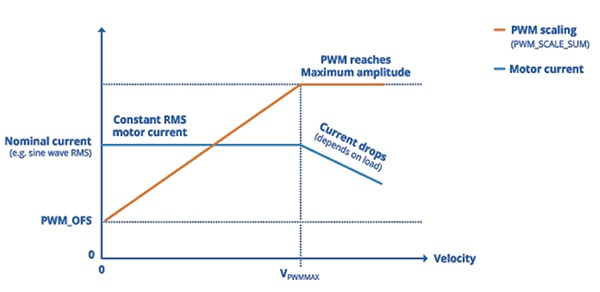 Figure 8: The StealthChop technique in the TMC5130A modulates the current drive based on the duty cycle, greatly reducing stepper motor audible noise. (Image source: Analog Devices)
For the second challenge, the TMC5130A uses SpreadCycle, a proprietary current-chopping technique. This cycle-by-cycle, current-based drive-chopping scheme implements slow decay of drive phases, which reduces electrical losses and torque ripple. It uses a hysteresis-based averaging of motor current to the target current, yielding a sine wave for the motor current, even at high speeds (Figure 9).
 Figure 9: The SpreadCycle cycle-by-cycle current-based MOSFET chopping scheme in the TMC5130A reduces electrical losses and torque ripple. (Image source: Analog Devices)
Other unique features of the TMC5130A are its StallGuard motor-stall detection and CoolStep dynamically adaptive current drive, with the latter leveraging the former.
StallGuard provides sensorless load detection via back electromotive force (EMF) and can stop a motor within one full step, thus protecting the motor driver and motor. As a further benefit, its sensitivity can be adjusted to match the application’s requirements. CoolStep adjusts the motor current based on the back-EMF StallGuard reading. It can reduce motor current by 75% in low-load situations, leading to power savings and less heat generation.
When driving two two-phase stepper motors rather than a single one, as supported by the TMC5130A, the TMC5072 is available with many of the same features (Figure 10). It can drive two independent coils with up to 1.1 A current per coil (1.5 A peak); the two drivers can also be paralleled to provide 2.2 A (3 A peak) to a single coil.
 Figure 10: The TMC5072 is a dual-driver version of the TMC5130A; the two independent outputs can be used in parallel. (Image source: Analog Devices)
FOC changes the scenario
There’s also the issue of position feedback from the motor. Stepper motors do not require feedback but often add it to assure high-precision control, while BLDC designs require it. Feedback is commonly implemented using an encoder (typically based on Hall effect sensors or optical encoders) but is limited by the update rate and resolution as well as the processing burden it adds to the system.
For BLDC motors, there is another control option. Field-oriented control (FOC)—also known as vector control (VC)—was devised to address issues related to feedback update rate and resolution, as well as encoder costs and installation issues.
In brief, FOC is a current-regulation scheme for motors that uses the orientation of the magnetic field and the position of the motor rotor. It is based on the “simple” observation that two force components act on the rotor of an electric motor. One component, called direct, or ID, is just pulling in a radial direction, while the other component, quadrature, or IQ, is applying torque by pulling tangentially (Figure 11).
 Figure 11: The principle which inspired FOC is the observation that a rotor is subject to two orthogonal forces, one radial to the rotor axis and the other one tangential. (Image source: Analog Devices).
The ideal FOC provides closed-loop control of current, resulting in a pure torque-generating current (IQ)—without direct current, ID. It then adjusts the drive-current strengths so that the motor provides the targeted amount of torque. One of FOC’s many features is that it maximizes active power and minimizes idle power.
FOC is an energy-efficient approach to controlling an electric motor. It works well with conditions of high motor dynamics and high speed, and it adds to intrinsic safety functionality due to its closed-loop control aspects. It uses standard resistor-based current sensing to measure the current magnitude and phase through the coils of the stator and the angle of the rotor. The measured angle of the rotor is then adjusted to the magnetic axes. The rotor angle is measured using a Hall sensor or position encoder so the direction of the magnetic field from the rotor is known.
However, there’s a long and extremely complex path from the FOC observations to a complete motor control scheme. FOC requires knowledge of some static parameters including the number of motor pole pairs, the number of encoder pulses per revolution, the encoder orientation relative to the magnetic axis of the rotor, as well as the count direction of the encoder, together with some dynamic parameters such as phase currents and the rotor orientation.
Further, the adjustment of the proportional and integral (P and I) parameters of the two PI controllers used for closed-loop control of the phase currents is dependent upon the electrical parameters of the motor. These parameters include resistance, inductance, the back EMF constant of the motor (which is also the torque constant of the motor), and the supply voltage.
The challenge facing designers when applying FOC is the high number of degrees of freedom in all parameters. While the flow charts and even source code for FOC are widely available, the actual “shippable” code needed to implement it is complex and sophisticated. It includes multiple coordinate transformations—the Clarke Transformation, the Park Transformation, the inverse Park Transformation, and the inverse Clarke Transformation—formulated as a set of matrix multiplications, as well as intensive repeated computation and calculation. There are many FOC tutorials available online, ranging from qualitative, equation-free/light ones to intensely mathematical ones; the TMC4671 datasheet falls in the middle and is worth reviewing.
Attempting to implement FOC via firmware requires substantial CPU compute power and resources and so constrains the designer with respect to processor selection. However, by using the TMC4671, designers can select from a much wider range of microprocessors and even low-end microcontrollers, while also being free from coding issues such as interrupt handling and direct memory access. All that’s required is a connection to the TMC4671 via its SPI (or UART) communication ports, as programming and software design is reduced to the initialization and setting of target parameters.
Don’t forget the driver
While some motor control ICs, such as the TMC5130A and TMC5072 for stepper motors incorporate motor gate-driver functionality with approximately 2 A drive, other ICs such as the TMC4671-LA for BLDC motors do not. For these situations, devices such as the TMC6100-LA-T half-bridge gate-driver IC add that needed capability (Figure 12). This triple half-bridge MOSFET gate driver comes in a 7 × 7 millimeter (mm) QFN package, provides up to 1.5 A drive current, and is suitable for driving external MOSFETs that handle up to 100 A of coil current.
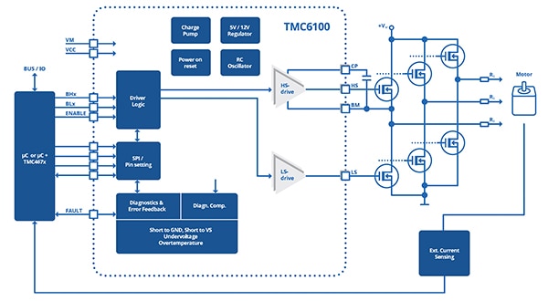 Figure 12: The TMC6100-LA-T half-bridge gate-driver IC provides up to 1.5 A drive current and is suited to driving external MOSFETs that provide up to 100 A of coil current. (Image source: Analog Devices).
The TMC6100-LA-T features software control of drive current for in-system optimization of its settings. It also includes programmable safety features such as short-circuit detection and overtemperature thresholds; together with an SPI interface for diagnostics, this supports robust and reliable designs.
To further speed time to market and ease the optimization of parameters and tuning of the driver, Trinamic offers the TMC6100-EVAL universal evaluation board (Figure 13). This unit provides convenient handling of the hardware, as well as a user-friendly software tool for evaluation. The system consists of three parts: a base board, a connector board with several test points, the TMC6100-EVAL, plus a TMC4671-EVAL FOC controller.
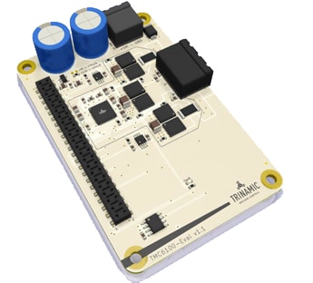 Figure 13: The TMC6100-EVAL universal evaluation board eases optimization of driver parameters and tuning of the driver to match the motor and load situation. (Image source: Analog Devices)
Conclusion
Video cameras for surveillance and security are a powerful tool for reducing physical travel and associated energy use. They often utilize PoE and are enhanced with motor-driven PTZ control, but this control function is complex. As shown, by integrating the various functions needed for effective motor control—and using gate drivers as needed—ICs from Trinamic provide smooth and precise movement and positioning for the brushless and stepper DC motors used for PTZ.
Trinamic offers engineers a wide range of solutions which accelerate implementation of efficient, precision motor-control systems tailored to the application needs. These products address the challenges in hardware, thus minimizing overall design and software complexity.
Related Content

Disclaimer: The opinions, beliefs, and viewpoints expressed by the various authors and/or forum participants on this website do not necessarily reflect the opinions, beliefs, and viewpoints of DigiKey or official policies of DigiKey.


