How to Accurately Sense Temperature Using Thermistors
Contributed By DigiKey's North American Editors
2020-04-21
Temperature is the most widely measured physical variable, and the thermistor is among the most popular sensors for measuring it. Thermistors—a merging of the words “thermal” and “resistor”—can be made of many different materials. Their basic physical principle is straightforward: resistance varies with temperature in a somewhat predictable and repeatable relationship. Further, since the thermistor looks electrically like a resistor, it can seem deceptively simple to measure: a suitable circuit interface requires only a fairly straightforward topology.
However, using a thermistor to measure temperature with consistency and accuracy involves a matrix of decisions related to voltage or current source drive, single and multipoint calibration, range and span, and the implications of different thermistor materials. This article will explore and explain thermistor issues, solution options, and tradeoffs. Sample devices from Murata Electronics will be used to help explain their operating principle, sample specifications, and their application. The article will also introduce and show how a new family of thermistors from Texas Instruments addresses some thermistor shortcomings.
So many measurement choices
Designers have many choices for contact temperature sensors: thermistors, resistance temperature detectors (RTDs), solid-state current sources, and thermocouples. Each has a different combination of attributes across key parameters, including temperature range, linearity, accuracy, sensitivity, power consumption, external circuitry, interfaces, and cost (Table 1). There’s no “ideal” temperature sensor, as each brings strengths and weaknesses relative to the others across these parameters.
 Table 1: This comparison of the four most common types of contact temperature sensors shows their relative attributes. Thermistors have the best sensitivity, struggle with linearity, but usually require relatively simple external circuitry. (Table source: DigiKey)
While the thermistor has somewhat inferior linearity and often needs per-unit calibration, it is nonetheless a very widely used temperature sensor. Electrically, it looks like a simple, basic two-terminal resistor, and its measured resistance is a monotonic function of the sensed temperature. Due to its popularity, it is available in many grades and package types including wire leads and surface mount technology (SMT).
Thermistor characteristics and parameters
As with any sensor, the thermistor has some top-tier parameters which designers must consider when selecting or using one. Some of these may seem non-intuitive or at odds with conventional sensor perspectives, but they can be managed with proper care to details.
Thermistors come in two basic types (Figure 1). One is usually made of a polycrystalline ceramic and has a negative temperature coefficient (NTC), with its resistance decreasing with temperature. The other is called a positive temperature coefficient (PTC) thermistor and is usually made of a semiconductor material. PTC, as its name implies, has a positive temperature coefficient. Note that the PTC and NTC device curves are not complementary “mirror images”. Instead, each has its own distinct curvature.
 Figure 1: The NTC and PTC thermistors have opposite and non-complementary resistance-versus-temperature curves, and both are highly nonlinear. Note the scale at the left is relative resistance, not absolute. (Image source: Ametherm, Inc.)
One obvious question is whether to use a PTC or an NTC thermistor in a given application. In some cases, the choice doesn’t matter as much as matching the specifications of the individual device to the application requirements. In general, the NTC device may be better for precision measurement. In contrast, PTC thermistors are typically used for current limiting or switching applications due to their rapid, distinctive increase in resistance, beginning at a specific temperature known as the Curie point. However, a new class of PTC devices is expanding the applicability of PTC devices. More on this later.
There is another situation where the choice between PTC and NTC devices may be critical. If the thermistor is being used directly in an analog closed-loop feedback configuration to maintain a variable setpoint, the slope of the resistance change versus temperature is critical and is a function of the control loop configuration.
For example, if the thermistor is part of a loop used to maintain a temperature setpoint by controlling current to a heating element, its resistance should increase with increasing temperature to reduce the current flow to the heater; thus, a PTC thermistor is the appropriate choice. Of course, if an NTC device is preferred for other reasons, the apparent slope can be reversed with an op amp configured as an inverting buffer.
Historical note: The first commercial product from Hewlett-Packard, the classic Model 200A audio oscillator, patented in 1942, used the large PTC of an incandescent bulb filament in a negative feedback loop to stabilize the amplifier output amplitude. Although not a thermistor in the formal sense, the filament acted as one, and the self-correcting circuit topology was a major innovation at the time.
Key thermistor performance parameters include:
• Nominal resistance at 25°C. Thermistors are initially categorized by their nominal value at that temperature on vendor selection guides. They can be fabricated with many different resistance values at that temperature by varying their specific composition. Thermistors are available with nominal values as low as 10 ohms (Ω) and as high as one megaohm (MΩ). Most applications use thermistors with a rating between 100 Ω and ten kilohms (kΩ) at 25°C.
• Sensitivity, which is a more detailed exposition of temperature coefficient. This parameter is not a constant, but instead is a function of temperature itself, as well as the composition of the thermistor. Defining it in detail is a key factor on the data sheet. It is also one of the factors that makes selecting and effectively using a thermistor more challenging in contrast to other sensors with constant or nearly constant temperature coefficient (tempco) values across their entire range.
A low sensitivity value can affect the precision of the temperature measurements. In general, NTC thermistors have very high sensitivity at low temperatures because of their exponentially nonlinear decrease in resistance. At high temperatures, however, their sensitivity drastically decreases, which can introduce incorrect temperature readings when combined with a high resistance tolerance. However, high sensitivity can also result in overranging and saturation of the analog front-end (AFE) and associated analog-to-digital converter (ADC) if the thermistor is measuring over a wide range. Thus, there is a tradeoff between sensitivity and range to be managed.
The temperature coefficient alpha (α, or A) is defined as the slope of the curve of resistance (R) versus temperature at a given point and is calculated using Equation 1:
![]() Equation 1
Equation 1
Where α is expressed in % per °C.
However, alpha itself is not constant, but is a function of where the thermistor is on the curve. To better characterize it, the industry has defined another constant factor beta (β or B), called the sensitivity index or constant of the material used. To get a rough approximation of R as a function of temperature over a defined sub-range, Equation 2 is used:
![]() Equation 2
Equation 2
β is used to develop a more accurate curve of resistance versus temperature, and a specification such as "3380 25/50" indicates a β constant of 3380 over a temperature range from 25°C to 50°C.
• Other parameters include the thermal time constant (TTC), which is the time it takes for the thermistor value to reach 63% of the difference between the old and new temperatures. There is also the thermal dissipation constant (TDC), related to the unavoidable self-heating which results from the current passing through the thermistor. TDC is the amount of power required to raise the thermistor temperature by 1°C and is specified in milliwatts per ˚C (mW/°C). In general, power dissipation should be kept as low as possible to prevent self-heating and subsequent errors.
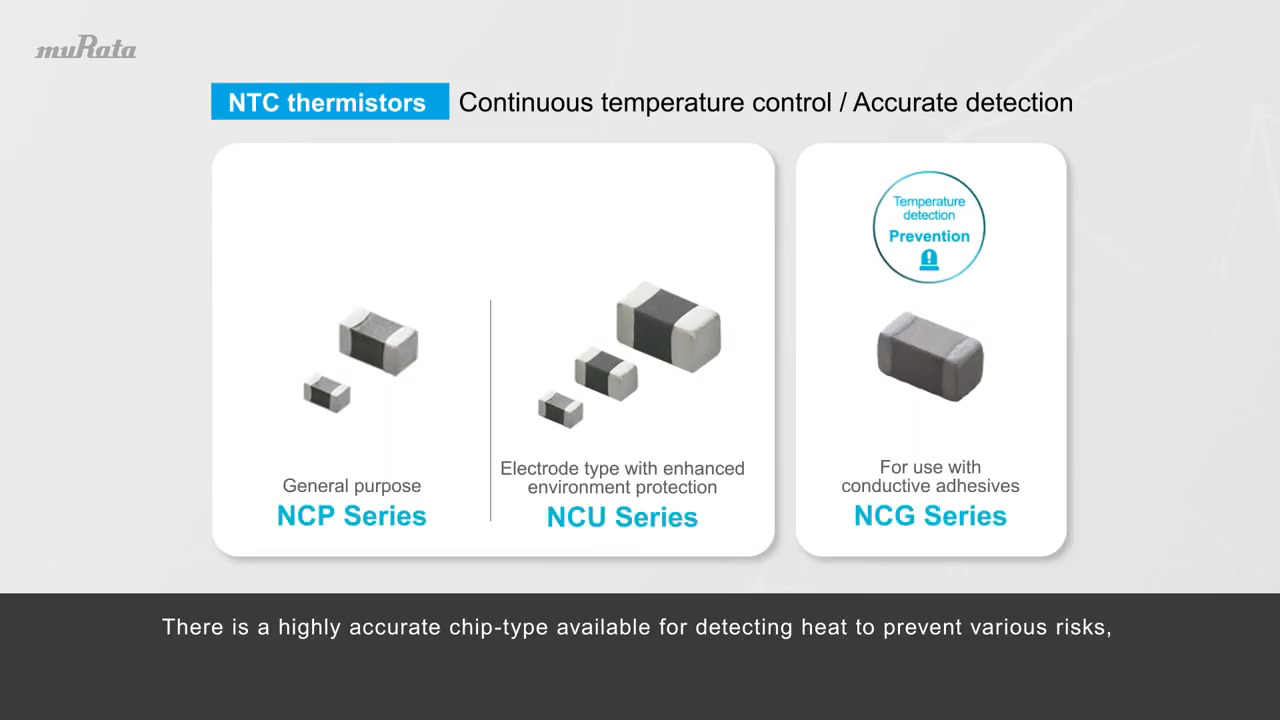
For example, the Murata NCP15XH103J03RC is a chip-scale SMT thermistor available in 0805, 0603, and 0402 packages, with the smallest measuring just 1.0 × 0.5 millimeters (mm). The critical β parameter is the same value for each size. The primary parameters for this 10 kΩ/25°C device are summarized in Table 2, which calls out β over different ranges; an associated chart also shows this information over temperature in Figure 2.
 Table 2: The most critical specifications when assessing a thermistor, such as the Murata NCP15XH103J03RC, include its nominal resistance at 25°C, tolerance, and B values at key temperatures. (Table source: Murata Electronics)
, temperature, and the R/R25 factor from -20°C to +120°C") Figure 2: This graph links β (B), temperature, and the R/R25 factor from -20°C to +120°C for the Murata NCP15XH103J03RC. (Image source: Murata Electronics)
Figure 2: This graph links β (B), temperature, and the R/R25 factor from -20°C to +120°C for the Murata NCP15XH103J03RC. (Image source: Murata Electronics)
Note that for thermistors—as with almost any component, regardless of how simple it appears at first or how few terminals it has—there are many other primary, secondary, and even tertiary level specifications to consider. For thermistors, many of these relate to initial tolerances of various specifications, as well as the temperature coefficients of those specifications.
Driving and sensing the thermistor
As it is a resistance-based sensor, driving a thermistor and sensing its resistance is fairly straightforward in principle. Unlike voltage sourcing temperature sensors such as thermocouples, the thermistor needs modest voltage or current excitation in order to measure its resistance. The simplest approach is to use a basic, constant voltage source and a voltage divider circuit (Figure 3). The output voltage (VTEMP) can be calculated using Equation 3:
![]() Equation 3
Equation 3
 Figure 3: A simple voltage source and resistor voltage divider arrangement is all that is needed in principle to measure the thermistor resistance corresponding to VTEMP. (Image source: Texas Instruments)
In practice, of course, it is often better to use a ratiometric or bridge topology to minimize the effect of power supply and bias resistance variation.
An alternate arrangement that is preferred in many designs when measuring resistance and changes in resistance is to use a constant current source (Figure 4). Here, VTEMP can calculated using Equation 4:
![]() Equation 4
Equation 4
 Figure 4: A current source is often used rather than a voltage source and divider due to its improved performance and control of the voltage reading. (Image source: Texas Instruments)
This provides superior linearity and better control over the sensitivity of the voltage across the thermistor.
The next issue relates to the AFE, which processes the voltage sensed across the thermistor. For thresholding and switched applications, it can be routed through a comparator to transition an output from high to low, or vice versa.
The situation is more complicated if the actual temperature value is needed, as is often the case. Now, issues of calibration and correction for the nonlinear behavior of the thermistor must be addressed. The output of the NTC and most PTC thermistors is somewhat predictable and highly nonlinear, and is characterized by a vendor supplied curve defining the resistance-temperature relationship for a given thermistor type.
Designers have several options for transforming the voltage reading, which represents the resistance, into an accurate temperature value:
• Designers can use a stepped array of multiple thermistors, with each one covering a small zone of the overall temperature range to create a piece-wise linear approximation. Further, by adding a resistor across each thermistor, the linearity of each thermistor is improved somewhat, but at a cost in terms of component cost, board space, inventory management, and power (Figure 5).
 Figure 5: Whether using a voltage or current source to drive the thermistor, adding a parallel resistor will improve its linearity, but at a penalty in component BOM and power use. (Image source: Texas Instruments)
• They can implement a piece-wise linear approximation in software, where the overall range is divided into many smaller ranges. The software can then use a simple linear equation with appropriate coefficients to linearize and correct the reading over each segment. This approach requires a moderate amount of processor resource and time, along with moderate memory needs.
• They can build a look-up table (LUT) which enumerates the resistance versus actual temperature. This uses minimal processor resources and time, but more memory proportional to the granularity of the look-up table. Interpolation can reduce the memory requirements at a modest computational cost.
• Finally, the system can use a complex curve-fitting equation which uses minimal memory but considerable processing resources.
For example, correction of readings for NTC thermistors can be done using the classic Steinhart-Hart equation, a curve-fit equation which accurately represents the R-T curve of the thermistor, which is shown in Equation 5:
![]() Equation 5
Equation 5
Where T is the temperature in Kelvin, R is the calculated resistance value, A, B and C are calculated coefficients determined by the designer or provided by the thermistor vendor; this is called a “three point calibration” for obvious reasons.
From the above, it’s clear that the various correction approaches require tradeoffs among circuity and components, needed memory, and processing resources.
Choosing the thermistor resistance range
Selecting a thermistor with the optimum resistance over the temperature range of interest is one of the challenges when using these devices. In some ways, it is analogous to sizing a resistor for the shunt resistor current sensing, but in other ways it is quite different.
The objective is to select a resistive device such that the voltage drop across it is the maximum the circuit can accept without overload. This maximizes the dynamic range, effective resolution, and signal-to-noise ratio (SNR). For the current shunt with its fixed resistor, the current versus voltage relationship is obviously linear. However, using a larger value resistor to accommodate this span also results in more self-heating at a given current level, which represents wasted power and also induces increased sensor self-heating.
Still, this shunt resistor/thermistor analogy also has differences. In the case of the current sensing shunt, the resistance is known while the current is the unknown. For the thermistor, the situation is reversed: the current from a current source or the voltage from a voltage source is known, but the resistance is the unknown variable. Since the resistance of the thermistor is a nonlinear function, it can suddenly and dramatically increase, causing the voltage across it to also increase, possibly beyond the acceptable value. This is especially the case with PTC thermistors as they approach their Curie point temperature. In short: the thermistor arrangement is not as clearly bounded as the current sensing shunt resistor design.
Tolerance and sensitivity drift are also factors. Thermistors have relatively large tolerances compared to the nominal values of their various parameters, so any modeling must include analysis with both root-mean-square (rms) and worst-case specifications to ensure the performance remains within circuit capabilities and error limits.
A new PTC thermistor overcomes long-standing issues
Designers have conflicting issues to weigh when using thermistors. On one side, they are inexpensive, have simple interface circuitry and are small; all beneficial for placement and responsiveness. On the other side, their calibration and accuracy issues can argue against their use in that they consume valuable design-in effort and require processor resources to achieve sufficient readings for most designs. Depending upon the robustness of execution of approaches to resolving these issues, the error can easily range from ±2˚C to twice that value.
This error is acceptable in a wide range of applications, but there are also many applications where this error is unacceptable. Stepping back, the basic challenges of using thermistors are their highly non-linear temperature sensitivity, along with inherent tolerances and specification drift. This combination often forces difficult tradeoffs and compromises which are seen in the modeling analysis.
A new family of silicon-based PTC thermistors from Texas Instruments, typified by the TMP6131DYAR, greatly minimizes many of these concerns. It expands the applicability of thermistors as it offers linearity and consistent sensitivity across temperature (Figure 6).
 Figure 6: The silicon-based TMP6131DYAR linear PTC thermistor from Texas Instruments offers linearity and consistent sensitivity across temperature. (Image source: Texas Instruments)
This ±1%, 10 kΩ (at 25°C) thermistor is offered in 0402 and 0603 package options with small thermal mass for fast response, while its low power operation minimizes self-heating, despite its small size. The TMP6131DYAR is designed for the range of -40°C to +125°C and so meets the vast majority of applications. It is also available in an automotive-qualified device grade, which makes sense as EV/HEV/ICE vehicles all have a large number of “hidden” temperature points which must be sensed and monitored.
Also, these silicon-based linear thermistors have a much more stable resistance tolerance as a result of their material composition and consistent resistance sensitivity. For example, a typical NTC thermistor has a much larger resistance tolerance as it moves away from 25°C than what its data sheet calls out at that temperature. In some cases, the resistance tolerance can increase from ±1% at 25°C to as much as ±4%, or more, at -40°C and 150°C.
In contrast, these silicon-based linear thermistors have much more consistent sensitivity values, enabling stable measurements across the whole temperature range. This characteristic is shown by the fairly linear R-T curve of the TMP6131DYAR in Figure 7.
 Figure 7: In sharp contrast to other PTC thermistors, the TMP6131DYAR has a nearly linear temperature versus resistance curve. (Image source: Texas Instruments)
An added benefit of this more linear behavior is that the complexity of the Steinhart-Hart equation is not needed for additional calibration of these silicon-based thermistors to achieve enhanced performance. Instead, calibration can be done using a much simpler fourth-order polynomial regression formula (Equation 6), which presents a greatly reduced processing burden.
![]() Equation 6
Equation 6
Where T is the temperature in Celsius, R is the calculated resistance value, and A (0–4) are the provided polynomial coefficients.
The relative attributes of traditional NTC thermistors compared to these silicon-based PTC devices is shown in Table 3.
 Table 3: The comparative attributes of the TI silicon-based PTC thermistors show distinct advantages over conventional NTC thermistors. (Table source: Texas Instruments)
Get up and running on the TMP6131DYAR
Thermistors are relatively easy to connect in a circuit, but they still require evaluation to fine-tune their performance to the application objectives. To accelerate the process, Texas Instruments offers the TMP6EVM, a prototype evaluation module (EVM) for the TTMP6131DYAR (Figure 8). The detailed user's guide describes the characteristics, operation, and use of the evaluation board, which also includes a multiline LCD display, so it can easily present messages to the user during setup and evaluation modes.
 Figure 8: The TMP6EVM evaluation module for thermistors such as the TMP6131DYAR eases their adoption for use in a specific target application. (Image source: Texas Instruments)
The EVM’s block diagram gives a clearer view of what it provides in Figure 9.
 Figure 9: A block diagram of the TMP6EVM evaluation module shows its self-contained design, including an LCD for interacting with the device. (Image source: Texas Instruments)
In addition to the evaluation board, TI also has a downloadable Thermistor Design Tool which offers complete resistance vs. temperature table (R-T table) computation, other helpful methods to derive temperature, and example C-code.
Conclusion
Thermistors are widely used, easy to connect, versatile sensors for measuring temperature. However, their inherent nonlinearities, tolerances, and drifts mean that designers must carefully study their data sheets, determine viable ranges, model their performance and error bounds, and implement a calibration scheme.
However, devices such as the TMP6131DYAR from Texas Instruments provide a silicon-based PTC solution for the widely used -40°C to +125°C range and do so with sufficient linearity and tight tolerance. In this way, they minimize many of the challenges associated with selecting and deploying conventional NTC or PTC thermistors.
Related Articles (DigiKey):
- Active Versus Passive Temperature Sensors: Designers Need to Choose Carefully
- Quickly Create an Accurate Thermistor-Based Temperature Sensing Circuit
- Effectively Sense Temperature in IoT Applications Using Solid State Technology
- Get High-Accuracy, Multi-Channel Temperature Measurements Regardless of Environment
References:
- Texas Instruments, “Temperature sensing with thermistors”
- Texas Instruments, “Improving temperature measurement accuracy in battery monitoring systems”
- Ametherm, Inc., “NTC Thermistor Beta”
- Ametherm, Inc., “The Secret To Successful Thermistor Beta Calculations”
- AVX/Kyocera, “TPCNTC/PTC Thermistors”
- TDK, “NTC Thermistors: General technical information”
- Bureau International des Poids et Mesures, “Guide on Secondary Thermometry: Thermistor Thermometry”
Disclaimer: The opinions, beliefs, and viewpoints expressed by the various authors and/or forum participants on this website do not necessarily reflect the opinions, beliefs, and viewpoints of DigiKey or official policies of DigiKey.