Get High-Accuracy, Multi-Channel Temperature Measurements Regardless of Environment
Contributed By DigiKey's North American Editors
2018-02-27
Although temperature measurement is a common requirement for many applications, developers face significant challenges in ensuring highly accurate results. Overcoming these challenges often leads to complex designs and extended design cycles, but new devices are reducing the complexity.
This article briefly discusses temperature measurement requirements and challenges associated with developing accurate solutions. The article then introduces the Linear Technology LTC2986-1 temperature sensor, describes how it addresses those challenges, and concludes by showing how developers can leverage those features in typical applications with various temperature sensors including thermocouples, RTDs, and thermistors.
Temperature measurement requirements and techniques
In building robust temperature measurement systems, designers draw on a variety of sensor types to meet their specific requirements for cost, accuracy, and temperature range. Among sensor types, thermocouples are commonly used in harsh environments with their ability to measure temperatures as low as -265°C to over 1800°C.
Thermocouples generate a voltage that is a function of the temperature difference between the tip and its cold junction – the end of two wires used to create the thermocouple. As a result, overall measurement accuracy depends on accurate measurement of both the thermocouple voltage and the cold junction.
While thermocouples generate voltage gradients due to the Seebeck effect, other common temperature sensors including resistance temperature detectors (RTDs), thermistors, and even diodes require an excitation current to produce a temperature-dependent voltage output. As resistive devices, RTDs and thermistors further require a precision sense resistor placed in series with the excitation current source. The sense resistor creates a resistor network with the resistive device for ratiometric measurement of the voltage across the sensor. Finally, for each type of sensor, developers need to apply appropriate methods for converting measured results to linearized temperature data using lookup tables or equations.
Besides dealing with the sensor, developers face multiple challenges in ensuring proper operation of the temperature measurement system. Temperature sensors are typically placed in locations exposed to harsh conditions in factories, commercial environments, buildings, and homes – wherever applications require the ability to measure temperature gradients in air or fluid flow. In industrial applications, long cable runs between sensor and measurement system inputs expose them to electrical noise, wear and tear, and external voltage sources that can damage both sensors and their measurement systems.
Engineers employ a variety of methods for dealing with the various factors that can impact performance in temperature measurement systems. As the need grows for larger numbers of temperature sensors, traditional approaches typically result in greater design complexity that increases costs in deployment and maintenance. The Linear Technology LTC2986-1 addresses these challenges, delivering accurate temperature measurements from multiple sensors with minimal effort on the part of the developer.
Reducing complexity
Designed to simplify design, the Linear Technology LTC2986-1 is a multi-channel temperature measurement system with built-in support for most sensor types including thermocouples, RTDs, thermistors, diodes, and active analog temperature sensors. Because this device integrates complete signal paths, conversion, linearization, and other features, developers can implement highly accurate temperature measurement designs with few additional components beyond the temperature sensors themselves (Figure 1). Although earlier members of the series such as the Linear Technology LTC2984 offer more input channels, the LTC2986-1 provides additional operating modes that enable unique solutions for enhancing accuracy as described below.

Figure 1: Designers can connect a wide variety of temperature sensors to the Linear Technology LTC2986-1, which provides ten input channels, programmable current sources, built-in linearization tables, and fault detection capabilities. (Image source: Linear Technology)
For RTDs, thermistors, and diodes, the device automatically generates excitation current at specified levels, measures the resulting sensor voltage, and generates a linearized result in °C or °F. The LTC2986-1 comes pre-programmed with conversion and linearization data for most RTDs and thermistors. Similarly, the device is preconfigured for nearly all standard thermocouples and supports cold junction compensation using RTDs, thermistors, diodes, or active analog temperature sensors. For temperature measurement, the device automatically solves the polynomial equations involved in converting thermocouple output voltage and cold junction measurements into a useful temperature reading. For more general conversion requirements, developers can use the LTC2986-1’s analog-to-digital converters (ADCs) to perform single-ended or differential voltage measurement, generating raw voltage results or converting results using a programmable lookup table.
Besides data for industry standard devices, the device can be used with custom RTDs, thermocouples, diodes, active sensors, and thermistors. For custom devices, developers load memory with a lookup table containing up to 64 data points representing sensor output values vs. temperature. For custom thermistors, developers can also directly load the device with up to six of the Steinhart-Hart coefficients typically provided by thermistor manufacturers. As with the built-in data for standard sensors, the device uses these custom coefficients and lookup tables for final temperature interpolation during the conversion process as well as soft-fault detection (Figure 2).
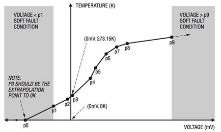
Figure 2: The Linear Technology LTC2986-1 can use developer-created lookup tables for custom devices, automatically generating faults when the input values fall outside the range of provided input data. (Image source: Linear Technology)
Enhanced accuracy and protection
For the conversion process, the device uses multiple cycles to provide greater accuracy. In normal operation, the device uses two conversion cycles to compensate for offset errors and noise before producing the final temperature result. Developers can also use the device in a three-cycle mode, which provides some benefits at the cost of slower measurement; about 251 milliseconds (ms) in three-cycle mode versus about 167 ms in two-cycle mode.
In three-cycle mode, the device can perform open circuit detection by generating a current pulse in the first cycle, followed by the normal two-cycle conversion process. If the device detects a large voltage during the subsequent conversion cycles, it will set a status bit to report a hard fault, indicating a likely broken thermocouple or cable. Additionally, the device is able to report a number of different fault conditions beyond hard faults from open circuits (Figure 3).
|
Figure 3: The Linear Technology LTC2986-1 generates hard and soft faults for all sensor readings, with additional results for cold junction measurements associated with thermocouple sensors as shown here. (Image source: Linear Technology)
Besides protecting applications from sensor faults, developers typically employ design techniques intended to protect the measurement system itself. Temperature sensors are often used in harsh environments. Sensors such as thermocouples are often unshielded, presenting a readily accessible conductive path to the input of the measurement system. Even with encapsulated sensors such as RTDs or thermistors, cables can become damaged creating a chance that the leads can short to high voltages or to each other. Finally, even careful operators and technicians can inadvertently make incorrect cable connections, particularly in applications designed to work with universal hardware connections for different sensor types.
To help protect the measurement system from overvoltage conditions, developers typically place current limiting resistors between the sensor and the input channel on the measurement system. Typically, designers add capacitors to create a low-pass filter to attenuate noise sources. These filters can extend settling time, which is particularly problematic in approaches using pulses of excitation current, as in the LTC2986-1 conversion process described earlier. Besides complications arising from settling time, the use of protection resistors can impact measurement accuracy.
The LTC2986-1 provides features and operating modes designed specifically to mitigate the secondary adverse effects of protection resistors. For example, to counter extended settling time due to larger filters on device inputs, developers can program additional delay in the device’s input multiplexer switching time. Providing perhaps greater impact on results, the device’s unique modes for excitation current address the more fundamental problem of increased series resistance associated with protection resistors.
Although critical for safety, protection resistors are particularly problematic for any resistive device such as an RTD or thermistor. In a two terminal resistive device, the addition of a protection resistor impacts voltage measurement as the excitation current flows through the additional series resistance of the protection component. Because the sensors are resistors, developers are typically faced with the challenge of separating sensor resistance from the additional series resistance associated with protection resistors and their leads.
To address this problem, engineers have employed 3-wire RTDs, using the resistance between one of the RTD terminals and the extra wire to measure lead resistance. Of course, this approach requires careful matching of lead length and series resistance to ensure accuracy. To avoid the matching problem, an even better solution employs 4-wire or Kelvin sensing, using a resistor at each terminal (Figure 4).
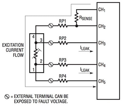
Figure 4: A conventional 4-wire RTD allows current to bypass the series resistors used to protect measurement channels (CH3 and CH4 here), so measurement error is limited due to the very low leakage current through those channels. (Image source: Linear Technology)
In this configuration, current follows a path (CH1 to CH5 in Figure 4) that does not involve the series protection resistors on the measurement channels (CH3 and CH4). Any current flowing through the measurement channels is limited to the device leakage current. Because input leakage current for the LTC2986-1 is less than 1 nanoamp (nA), associated measurement errors typically fall well below any required resolution levels.
With the LTC2986-1, however, this approach is not limited to 4-wire RTDs. Engineers can configure the device to perform Kelvin sensing with 3-wire RTDs, 2-wire RTDs, and thermistors.
For each of these sensor types, the LTC2986-1 provides a unique excitation mode that uses an adjacent channel for the current path. To implement this mode, developers connect an additional protection resistor between each sensor terminal and a separate LTC2986-1 input. They then enable this additional current path by simply setting a bit in the LTC2986-1 configuration register and configuring input channels appropriately (Figure 5). As with a more conventional 4-wire device, the excitation current avoids the measurement channel, reducing measurement error accordingly.

Figure 5: Developers can configure the Linear Technology LTC2986-1 to use an adjacent channel for the excitation current path, providing the benefits of Kelvin sensing to 2-wire RTDs and thermistors. (Image source: Linear Technology)
Regardless of whether or not designers use this alternative excitation mode, they still need to follow a basic protocol for setting up sensors with the LTC2986-1. To implement sensor connections, they need to assign channels and load associated memory locations with sensor configuration data (Figure 6). This channel assignment data resides in sequential locations in RAM, with a one-to-one correspondence to each of the device’s ten input channels. After the RAM has been programmed, developers can preserve the configuration in the device’s built-in EEPROM for restoration after subsequent power down or sleep cycles.
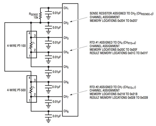
Figure 6: To configure the Linear Technology LTC2986-1, developers create channel assignment data blocks containing details of the associated sensor. (Image source: Linear Technology)
Within each block of channel assignment data in memory, developers define details of the sensor configuration including predefined values for sensor type, channel, sensor configuration, excitation current, and standard or custom conversion information. The memory map for one device, the PT-100 RTD shown on the top left of Figure 6, is illustrated (Figure 7).
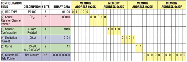
Figure 7: Channel assignment data contains configuration details about each sensor – here, showing the memory map associated with the PT-100 RTD, shown on the top left of Figure 6. (Image source: Linear Technology)
Configuring appropriate memory maps for each channel in a complex multi-sensor temperature system requires careful attention to each detail. Because the device has built-in support for a broad array of sensors and sensor types, developers need to ensure selection of the correct code for their particular sensor. Errors in configuration would likely seriously compromise the results.
To eliminate manual configuration, Linear Technology provides a free Windows®-based LTC2986 demo software program that lets developers specify configurations by using pulldown menus with options available for each channel. Developers can load configuration examples from a demo board or from specific diagrams shown in the LTC2986-1 datasheet (Figure 8).
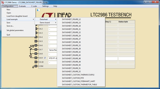
Figure 8: The Linear Technology LTC2986 demo software simplifies device use, providing pulldown selection of predefined configurations for associated hardware boards and from examples in the LTC2986-1 datasheet. (Image source: Linear Technology)
For example, the two 4-wire RTD configuration shown in Figure 6 above is taken from Figure 22 in the LTC2986-1 datasheet. Selecting that figure from the program’s configuration pulldown menu produces the corresponding settings for that configuration (Figure 9).
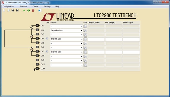
Figure 9: The Linear Technology LTC2986 demo software produces detailed configurations used in turn for generating channel assignment data. (Image source: Linear Technology)
Besides simplifying creation of configurations, the program can evaluate custom configurations to ensure correct assignments. Most importantly, the program can generate a corresponding set of C language headers and software routines that can be executed with no further effort on Linear Technology’s DC2026 Arduino compatible Linduino One board.
For example, the generation of C code for the configuration shown in Figure 9 automatically generates an initialization routine containing the software assignment that implements the required memory map shown back in Figure 7. As shown in Listing 1, the generated code uses an accompanying set of defined constants to create appropriate channel assignment statements (Listing 1).
Copy
   .  .  .
void configure_channels()
{
  uint8_t channel_number;
  uint32_t channel_assignment_data;

  // ----- Channel 2: Assign Sense Resistor -----
  channel_assignment_data =
    SENSOR_TYPE__SENSE_RESISTOR |
    (uint32_t) 0x9C4000 << SENSE_RESISTOR_VALUE_LSB;            // sense resistor - value: 10000.
  assign_channel(CHIP_SELECT, 2, channel_assignment_data);
  // ----- Channel 4: Assign RTD PT-100 -----
  channel_assignment_data =
    SENSOR_TYPE__RTD_PT_100 |
    RTD_RSENSE_CHANNEL__2 |
    RTD_NUM_WIRES__4_WIRE |
    RTD_EXCITATION_MODE__ROTATION_SHARING |
    RTD_EXCITATION_CURRENT__100UA |
    RTD_STANDARD__ITS_90;
  assign_channel(CHIP_SELECT, 4, channel_assignment_data);
  // ----- Channel 7: Assign RTD PT-500 -----
  channel_assignment_data =
    SENSOR_TYPE__RTD_PT_500 |
    RTD_RSENSE_CHANNEL__2 |
    RTD_NUM_WIRES__4_WIRE |
    RTD_EXCITATION_MODE__NO_ROTATION_SHARING |
    RTD_EXCITATION_CURRENT__50UA |
    RTD_STANDARD__AMERICAN;
  assign_channel(CHIP_SELECT, 7, channel_assignment_data);

}
   .  .  .
// -------------- Run the LTC2986 -------------------------------------

void loop()
{
  measure_channel(CHIP_SELECT, 4, TEMPERATURE);      // Ch 4: RTD PT-100
  measure_channel(CHIP_SELECT, 7, TEMPERATURE);      // Ch 7: RTD PT-500
}
Listing 1: Code generated by the Linear Technology LTC2986 demo software program automatically produces channel assignment statements, including the channel 4 assignment corresponding to the memory map shown in Figure 7. (Code source: Linear Technology)
Whether using the Linduino platform or other hardware, the generated code set demonstrates the key design patterns associated with use of the LTC2986-1. For example, the code fragment in Listing 1 illustrates a basic loop for data collection. By inspecting the generated code, developers can examine detailed operations involved in device usage. For example, the top-level function x measure_channel shown in Listing 1 calls lower level routines that access device registers to start conversion, wait for completion, and read the result (Listing 2). In this case, the generated programs simply print the results to the console, but developers can easily modify the code for their applications.
Copy
// *****************
// Measure channel
// *****************
void measure_channel(uint8_t chip_select, uint8_t channel_number, uint8_t channel_output)
{
    convert_channel(chip_select, channel_number);
    get_result(chip_select, channel_number, channel_output);
}


void convert_channel(uint8_t chip_select, uint8_t channel_number)
{
  // Start conversion
  transfer_byte(chip_select, WRITE_TO_RAM, COMMAND_STATUS_REGISTER, CONVERSION_CONTROL_BYTE | channel_number);

  wait_for_process_to_finish(chip_select);
}

   . . .

void wait_for_process_to_finish(uint8_t chip_select)
{
  uint8_t process_finished = 0;
  uint8_t data;
  while (process_finished == 0)
  {
    data = transfer_byte(chip_select, READ_FROM_RAM, COMMAND_STATUS_REGISTER, 0);
    process_finished  = data & 0x40;
  }
}


// *********************************
// Get results
// *********************************
void get_result(uint8_t chip_select, uint8_t channel_number, uint8_t channel_output)
{
  uint32_t raw_data;
  uint8_t fault_data;
  uint16_t start_address = get_start_address(CONVERSION_RESULT_MEMORY_BASE, channel_number);
  uint32_t raw_conversion_result;

  raw_data = transfer_four_bytes(chip_select, READ_FROM_RAM, start_address, 0);

  Serial.print(F("\nChannel "));
  Serial.println(channel_number);

  // 24 LSB's are conversion result
  raw_conversion_result = raw_data & 0xFFFFFF;
  print_conversion_result(raw_conversion_result, channel_output);

  // If you're interested in the raw voltage or resistance, use the following
  if (channel_output != VOLTAGE)
  {
    read_voltage_or_resistance_results(chip_select, channel_number);
  }

  // 8 MSB's show the fault data
  fault_data = raw_data >> 24;
  print_fault_data(fault_data);
}
Listing 2: The Linear Technology LTC2986 demo software generates Linduino ready code, including support routines such as shown in this snippet for performing low-level access to device channels. (Code source: Linear Technology)
Along with the software, developers can quickly get started with LTC2986-1 hardware development using the Linear Technology DC2608A kit. Designed to work with the Linduino, the DC2618 kit includes a demo board containing the LTC2986-1 as well as a breadboard. Used in combination with the LTC2986 demo software, the kit provides a platform for rapid development of temperature sensing applications.
Conclusion
Typically required to operate in harsh environments, temperature measurement systems present developers with a wide array of challenges, including conflicts between protection mechanisms and measurement accuracy. Using the LTC2986-1 and associated development tools, engineers can now rapidly implement systems capable of safe, accurate temperature measurement.

Disclaimer: The opinions, beliefs, and viewpoints expressed by the various authors and/or forum participants on this website do not necessarily reflect the opinions, beliefs, and viewpoints of DigiKey or official policies of DigiKey.


