Creating a Custom Wireless Programmable Logic Controller (PLC)
Contributed By DigiKey's North American Editors
2018-06-27
The industrial IoT is growing fast, but industrial engineers need custom flexibility and connectivity beyond what is offered by traditional programmable logic controllers (PLCs). However, custom building a solution can be expensive and time consuming with few industrial engineers having the experience to implement a truly embedded solution based on a microcontroller.
This article is a quick introduction to PLCs before showing how developers can create their own wireless PLC which can use ladder logic for implementing applications.
Introduction to programmable logic controllers (PLCs)
A PLC is a ruggedized computer used to automate a specific process in an industrial application. The process that is being automated can range from the assembly line in a manufacturing plant through an IoT building lighting control system and everything in between.
A typical PLC architecture includes (Figure 1):
- A central processing unit with internal RAM and ROM
- Digital and analog inputs
- Digital and analog outputs
- Industrial rated power supplies
- Logic application to execute the desired behaviors
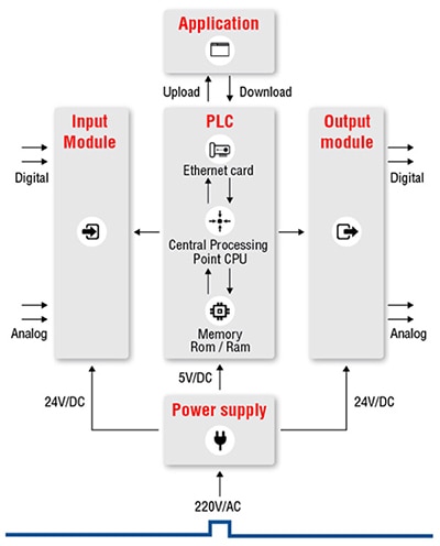
Figure 1: A typical PLC architecture contains a series of analog and digital inputs that are processed and executed against a logic application that then drives the behavior for its analog and digital outputs. (Image source: Unitronics)
While there are many options available on the market for the traditional PLC, developers may find that they want to customize the PLC behavior or custom build a device of their own. There are several different ways to do this, but one interesting way that a traditional embedded systems engineer can do this easily is to use the STM32 Open Development Environment (ODE).
Building a wireless PLC
There are three primary hardware components that a developer needs to build their own wireless PLC:
- A CPU
- Input/output signal conditioning
- A Wi-Fi module
A developer could start from scratch and design all these components, or they could leverage an existing ecosystem. STMicroelectronics has simplified creating a PLC by producing an STM32 developer pack that includes each of these components, and also provides baseline software to develop ladder logic applications.
Let’s now examine these primary components and the conditions they need to meet in order function in an industrial environment.
The first component to examine is the CPU, which in this case is an STM32F401RE from STMicroelectronics. The STM32F401RE is a 32-bit Arm® Cortex®-M4 processor that runs at 84 MHz, has 512 Mbytes of flash space for application code, and 96 Kbytes of RAM. The STM32F401RE is provided on the Nucleo-401RE evaluation board which also includes Arduino headers to interface to other hardware, and an ST-Link for programming the embedded software. The Nucleo-401RE is where all the PLC code will execute.
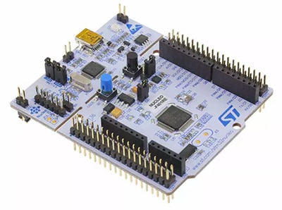
Figure 2: The Nucleo-401RE development board forms the base for the PLC controller and contains 512 Mbytes of application code space and 96 Kbytes of RAM for data. (Image source: STMicroelectronics)
The second component that is necessary to build a PLC is a signal conditioning board for inputs and outputs. Developers have two boards that they can choose between or combine if the application calls for it.
The first is the X-Nucleo-PLC01A1 industrial I/O expansion board (Figure 3). The X-Nucleo-PLC01A1 contains eight conditioned inputs through a CLT01-38SQ7 high-speed digital input limiter. The CLT01-38SQ7 provides digital input protection for the PLC by limiting the current that can be consumed by the input pin. There are also eight industrial outputs that are conditioned using a VNI8200XP monolithic 8-channel driver. This features a very low supply current, with integrated SPI interface and high efficiency 100 mA micropower step-down switching. The VNI8200XP provides eight solid state relays on-chip that can each drive up to 0.7 amps. The X-Nucleo-PLC01A1 also includes an LED indicator to visually see the state for each input and output, and three alarm lights to signal over temperature and other board faults. The X-Nucleo-PLC01A1 communicates to the Nucleo-401RE through an SPI communication link.
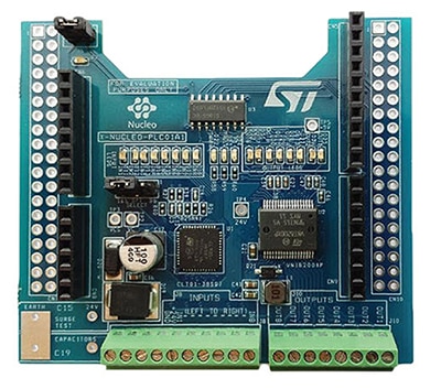
Figure 3: The X-Nucleo-PLC01A1 is an industrial grade board designed to provide a PLC application with eight digital inputs and eight digital outputs. (Image source: STMicroelectronics)
A PLC may also require the ability to control high current and analog signals. The X-Nucleo-PLC01A1 is designed only for digital signals. In order to control these other signals, a developer could use the X-Nucleo-OUT01A1 (Figure 4). The X-Nucleo-OUT01A1 contains the STMicroelectronics’ ISO8200BQ galvanically isolated octal high-side smart power solid state relay. The big difference here when comparing these outputs to the PLC01A1 is that the board can operate on voltages ranging from 10.5 to 33 volts, with galvanic isolation between the analog and digital signals. There are also several LED indicators on board to indicate if a communication failure or a thermal protection event has occurred.

Figure 4: The X-Nucleo-OUT01A1 is an industrial grade board designed to provide a PLC application with eight relay outputs that can handle up to 0.7 amps. (Image source: STMicroelectronics)
The final component that could be used to provide a wireless programming mechanism or be used to create an IoT connected PLC is a wireless chip. Developers can use the X-Nucleo-IDW01M1 which is an 802.11 b/g/n compliant Wi-Fi expansion module, also from STMicroelectronics (Figure 5). The X-Nucleo-IDW01M1 is FCC, IC and CE certified with an integrated antenna which makes it drop in ready for a production system.
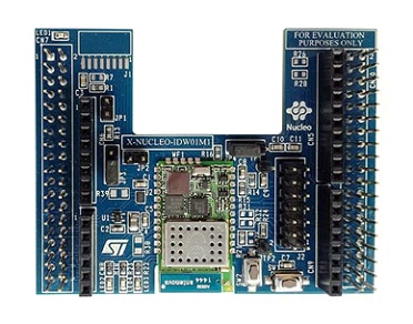
Figure 5: The X-Nucleo-IDW01M1 is an industrial grade Wi-Fi module that can be integrated into a PLC to provide wireless connectivity. (Image source: STMicroelectronics)
With each of these components on hand, a developer can assemble their hardware PLC in the order shown in Figure 6. It is possible to install the boards backwards which won’t damage them, but will result in some additional debugging. Just in case there is any custom hardware that needs to be added to the PLC, such as an RS-485 chip, developers can use an Arduino prototyping shield such as the Proto Shield from Olimex or the Adafruit Proto Shield.
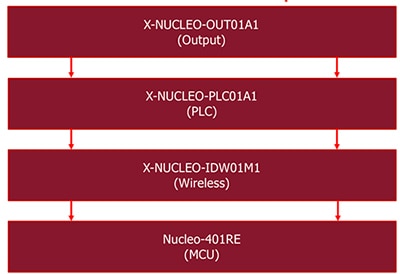
Figure 6: The order in which to assemble the STMicroelectronics development boards to achieve a functional PLC. (Image source: Beningo Embedded Group)
Setting up the PLC software
There are several pieces of software that are required in order to setup the PLC. These include:
- The PLC embedded software
- An embedded compiler
- A ladder logic application
The PLC embedded software FP_IND_PLCWIFI1 was developed by STMicroelectronics and is available for download from the STM website. It contains all the code needed to get the STM32F401RE up and running, and contains several preset configurations depending on which hardware stacks are needed. The embedded software comes with three projects already setup for the STM System Workbench, IAR Workbench and Keil MDK, and can be downloaded from http://www.st.com/en/embedded-software/fp-ind-plcwifi1.html (Figure 7). A developer can use any of these to compile and deploy the embedded software on the PLC.

Figure 7: The embedded PLC application package that is required to run the PLC. (Image source: Beningo Embedded Group)
Once the embedded application has been downloaded, it can be imported into the desired compilers IDE and compiled. A developer should find that the code compiles without issue. The compiled application can then be downloaded to the PLC using a standard USB connection to the PC.
Finally, STMicro also created a simple PLC application program that can be used to create logic ladder applications. This application is available for both iOS and Android. The application can be downloaded on the mobile devices by searching for ST PLC App in the application stores for the mobile device.
A simple example application
Once the embedded software for the PLC is running, a developer can focus on developing their application code using the ST PLC application. The application code will be developed using ladder logic. A developer can launch the application and create a new project based on the development boards they have selected to include in their hardware stack (Figure 8).
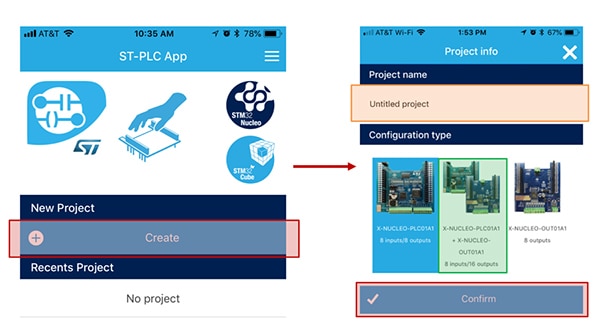
Figure 8: From the ST PLC application, a developer can create a new project (left red highlight), select the project name (right orange), and then configure the hardware that is being used (right green). (Image source: Beningo Embedded Group)
Once the project has been configured, a developer has a clean slate to create the ladder rungs for their application. A good first project is to simply test whether an input can be read, and an output set based on that input. A developer can create this test by clicking “Add rung”, and then implementing the logic necessary within the application. Once this is done, a developer would have created a rung similar to the left side in Figure 9.
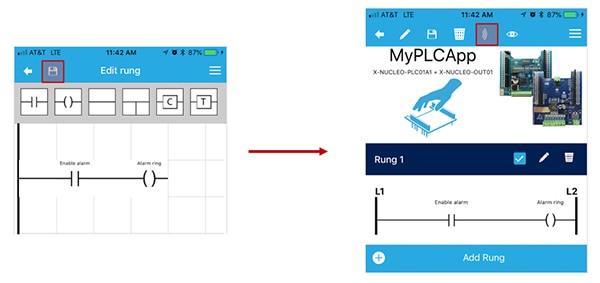
Figure 9: From the ST PLC application, a developer can implement their logic to control their device as they desire (left). Once the application has been created, it can be pushed wirelessly to the PLC by clicking the send application button (right). (Image source: Beningo Embedded Group)
Saving the rung then brings a developer back to the main project screen. From here, they can edit a rung or create additional rungs in the application. If the application is ready to be deployed, clicking the wireless transmit button shown on the right side of Figure 9 will connect and then transmit the PLC application. Note that a developer does need to have their mobile device connected to the PLC access point, and have configured their port and IP address in order for the application transmission to be successful.
Tips and tricks for building a wireless PLC
There are several tips and tricks that developers can follow when creating their own custom wireless PLC. These include:
- If the wireless board is not working, verify that the board is oriented correctly on the stack. (i.e. was put on in the right direction)
- Improving the systems security by adding a security key to the SSID.
- Update the PLC by changing the default wireless behavior to be station mode and only during an update switch to access point.
- Consider adding industrial communication protocols such as RS-485 and Modbus.
- The best way to get up to speed on PLCs is to think of an interesting problem and then try to solve that problem with the PLC.
- Use the IAR Embedded Workbench for Arm to compile the PLC embedded software. The toolchain is code unlimited for 30 days.
Conclusion
Building a custom PLC doesn’t necessarily need to be difficult. As shown, the ecosystem provided by STMicroelectronics allows a developer to get base PLC software up and running extremely quickly. The application can then be easily modified and customized to meet a wide range of applications and challenges.
While the primary goal would be to create the end application code using ladder logic, if a developer has the experience and knowledge, they can easily make adjustments to the embedded software and have a hybrid system that is far more powerful and flexible.

Disclaimer: The opinions, beliefs, and viewpoints expressed by the various authors and/or forum participants on this website do not necessarily reflect the opinions, beliefs, and viewpoints of DigiKey or official policies of DigiKey.


