Compact CCS Cables Provide Level 2 Fast DC Charging
Contributed By DigiKey's North American Editors
2022-10-18
Convenient and reliable charging is needed to eliminate the “range anxiety” associated with electric vehicles (EVs). To support those needs, designers of EV service equipment (EVSE) infrastructure need to include a variety of charging options including medium-power, Level 2, direct current (DC) fast chargers in residential, commercial, and retail settings that can deliver up to 80 amperes (A); high-power, Level 3, ultra-fast chargers that can deliver up to 500 A DC; and lower power, Level 1, alternating current (AC) charging for overnight and emergency charging.
However, DC charging of EVs is complex. The EVSE needs to continuously monitor the connector lock, system isolation, charging voltage, charging current, and connector temperature. If any of those parameters fall outside their set limits, the EVSE shuts down. Also, designing, assembling, and ensuring the long-term mechanical and electrical integrity of a compact cable and connector for Level 2 DC chargers can be challenging. The cable includes 5 conductors: +DC, -DC, communications, lock monitor, and protective earth. These conductors must be reliably connected to the EVSE on one end and the compact charging system (CCS) connector on the other. If any of these connections are faulty, the EVSE will likely require expensive and time-consuming rework to ensure reliable operation.
To address concerns around the assembly of CCS connectors and cables for Level 2 EVSEs, designers can use preassembled compact CCS connectors with attached cables. These cable and connector assemblies are designed for use in locations where Level 3 charging is not needed, but faster Level 2 is preferred over Level 1. These cables are available in Type 1 for North America and Type 2 for Europe, with Type 1 meeting the requirements of UL2251.
This article reviews the differences between AC and DC CCS connectors and cables and compares Level 2 and Level 3 DC CCS connectors in terms of size and convenience. It also discusses several use cases for medium-power CCS cable assemblies, and then presents Type 1 and Type 2 CCS compact cable assemblies from Phoenix Contact, along with installation recommendations.
The difference between AC and DC EV charging cables
CCS standard charging inlets are designed to accept both AC and DC charging connectors, providing flexibility while simplifying EV design. AC charging is inherently lower power and uses cables with pluggable connectors on both ends (Figure 1). For DC charging, which operates at higher power levels, the charging cable is always connected to the EVSE on one end, with a connector on the other end that is inserted into the vehicle’s receptacle. In addition, DC connectors have safety features not found in their AC counterparts, including locking mechanisms and temperature monitoring.
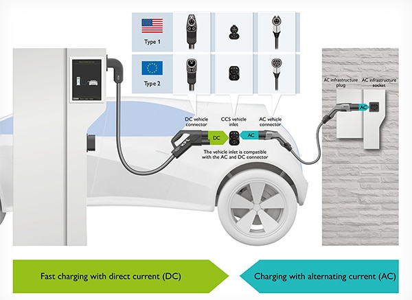 Figure 1: Cables for DC charging are permanently attached to the EVSE and are plugged into the EV receptacle. Cables for AC charging have plugs on both ends. (Image source: Phoenix Contact)
The CCS connectors for Level 2 and Level 3 DC charging up to 250 kilowatts (kW) are similar in size and can be used in a common vehicle inlet. The primary difference is about a 50% increase in the cable diameter for 250 kW rated units to carry the higher power levels, along with a corresponding increase in cable weight. As a result of the much smaller cable, the Level 2 connector and cable assemblies rated for up to 80 kW are significantly lighter and easier to handle. High power DC charging up to 500 kW or more requires a different vehicle inlet that supports liquid cooling, as well as a larger connector and cable (Table 1).
|
Table 1: Size comparison of Type 2 CCS connectors and cables rated for 80 kW, 250 kW, and 500 kW rated DC chargers. (Image source: Phoenix Contact)
Locking mechanisms are integrated into CCS DC charging connector systems for user safety and to ensure proper operation of the EVSE. These locks are designed to withstand high pull-out forces, making it nearly impossible to disconnect the connector while the EV is being charged. The locking mechanism in Type 1 connectors is a manual clip, as shown in Figure 2. In Type 2 connectors, locking is accomplished using a metal bolt that is electromagnetically controlled. In both cases, the locking mechanism is monitored, and its state is communicated to the EVSE through a dedicated connection.
 Figure 2: Type 1 CCS connectors include a manually operated locking clip. (Image source: Phoenix Contact)
Integrated temperature sensing is required in CCS DC charging connectors. With precise temperature monitoring directly at the power contacts, the charging process can be stopped or slowed down in the event of overheating to protect the user from danger and the EVSE from damage. These connectors include two PT1000 sensors, one on each contact (Figure 3). These sensors have a resistance that increases linearly with increases in temperature, simplifying temperature monitoring. The temperature is communicated to the EVSE through a signal line in the cable.
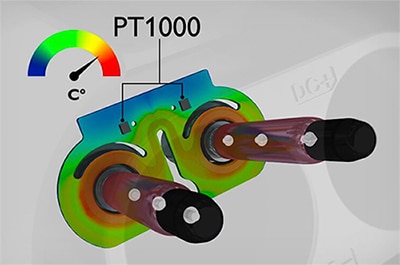 Figure 3: PT1000 temperature sensors are required on the CCS connector contacts to monitor operating temperature and help ensure safe charging. (Image source: Phoenix Contact)
Secure connections
The connections inside the CCS connector are especially important. The connections internal to the EVSE are not subject to significant mechanical stresses, but the CCS connector will be mated and unmated on a regular basis, and the cable connections will be subject to repeated stresses (Figure 4). Improperly attached connector cables can result in contact degradation in the form of increased resistance or loss of cable attachment, causing overheating or momentary loss of connection of one or more conductors. Inadequately assembled connector cables will result in reduced reliability of the charging system, user dissatisfaction, and possible warranty expenses for EVSE makers.
 Figure 4: The small size of the connectors for medium power DC charging makes it challenging to ensure robust and reliable cable connections. (Image source: Phoenix Contact)
Level 2 use cases
Level 2 DC charging is expected to be popular where more power is needed than can be supplied by AC charging, and faster Level 3 charging is not necessary. The EVSEs using these compact connectors meet CCS standards, and the smaller form factor enhances convenience and ease of use. They are expected to be found in a range of applications including:
Suburban residential: Level 2 DC chargers use 240-volt AC (Vac) power and can recharge a battery pack three to seven times faster than a basic Level 1 AC charger, depending on the EV. An added benefit is that for homes with solar panels, Level 2 DC chargers can transfer DC power directly from the solar array, eliminating conversion power loss. In the future, as vehicle-to-grid (V2G) and vehicle-to-home (V2H) systems become more common, bidirectional Level 2 chargers will be available that will control reverse power flow from the vehicle to the home or the grid.
Multi-family housing and urban: Apartment complexes and condominium communities are providing Level 2 DC chargers for residents and visitors. In addition, so-called “right of way” charging in urban residential settings includes chargers serving on-street parked cars when there are no garages available. In both cases, the charger can provide a revenue stream to the EVSE owner and convenience to EV owners in the neighborhood.
Public places where cars congregate: Level 2 DC chargers are being installed at a growing variety of public places such as shopping and entertainment centers, schools and colleges, parking structures, sports arenas, gas stations, and repair shops. As EV sales continue to rise, Level 2 DC chargers are also being found at car dealerships. These chargers are used to make sure EVs are fully charged before delivery to customers and for recharging EVs left for service.
Level 2 DC connector solutions
When charging current up to 80 A is needed, EVSE designers can turn to the lightweight CCS C-Line DC charge connector and cable assemblies from Phoenix Contact. They are available with various cable lengths for Type 1 and Type 2 applications. For example, charging cable 1236308 has a Type 1 connector and a cable measuring 4 meter (m) in length, and charging cable 1236966 has a Type 2 connector and a cable that is 7 m long. These ergonomic connectors meet all CCS standards in a small form factor to facilitate quick connects and disconnects for use in a range of low-power charging applications (Figure 5). If desired, they can be supplied with a company logo to enhance EVSE branding. Even though they are small in size, they are high performance and include:
- Silver-plated contacts for optimum performance and reliability
- Integrated sensors to monitor the temperature of the power contacts, as well as integrated locking mechanisms, per the CCS standard
- Compliance with DIN EN 50620, plus extruded insulation and sheaths rated up to 750 volts for use in severe environments when connecting the EVSE with the EV
- Compatibility with the requirements of IATF 16949 automotive standard and ISO 9001
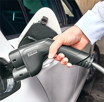 Figure 5: The ergonomic shape of the CCS C-Line connectors, plus their lightweight cabling, facilitates ease of handling and convenience. (Image source: Phoenix Contact)
EVSE integration
To support the integration of C-Line cable assemblies into EVSEs, Phoenix Contact provides designers with connector holders and cable glands, including the 1624143 connector holder and the 1424483 cable gland for Type 1 connectors, and the 1624153 connector holder and 1411134 cable gland for Type 2 connectors. Installing connector holders on the side or front of the EVSE provides a secure place for a connector when it’s not in use. The connector locks into place but can be easily removed. The holder has the flexibility to be mounted with 0˚ to 45˚ of frontal inclination. The use of a cable gland protects the cable as it passes through the wall of the EVSE, protects the cable from damage if the user pulls on it, and prevents the entry of dirt and moisture into the EVSE.
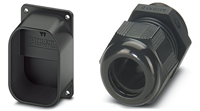 Figure 6: Connector holders (left) and cable glands (right) for Type 2 connectors facilitate the integration of CCS C-Line connector and cable assemblies into EVSEs. (Image source: Phoenix Contact)
Conclusion
Level 2 DC charging can provide a valuable alternative to lower power Level 1 charging. However, the design of DC charging cabling and connectors comes with many performance, safety, and regulatory challenges. As shown, by using off-the-shelf cable/connector assemblies for Level 2 charging, designers can quickly address many of these challenges, along with built-in advantages such as lighter weight and ergonomic design for greater ease of use.
Recommended reading

Disclaimer: The opinions, beliefs, and viewpoints expressed by the various authors and/or forum participants on this website do not necessarily reflect the opinions, beliefs, and viewpoints of DigiKey or official policies of DigiKey.


