Combine PoE with Bluetooth Low Energy to Cost Effectively Implement a Smart Lighting Infrastructure
Contributed By DigiKey's North American Editors
2020-08-20
Smart lighting combines efficient and long-lasting LEDs with wireless connectivity that allows building managers to customize lighting to suit occupancy and minimize energy use. Installing smart lighting in new buildings is relatively straightforward but retrofitting to existing buildings is complex and far more expensive. Building managers of established properties are looking for cheaper alternatives that enable them to take advantage of advances in illumination.
A simple, cost-effective alternative is to add Power-over-Ethernet (PoE) to existing Ethernet networks to power LEDs. The downside is that Ethernet is less suited for connectivity of smart lighting because it was designed for transferring frequent, high volumes of information between computers rather than the small, infrequent data transmissions used for the control and configuration of smart lighting.
The solution is to combine PoE with Bluetooth Low Energy (LE) connectivity for wireless configuration and control from smartphones. This short-range RF standard has already seen widespread adoption for smart lighting, and crucially, is interoperable with smartphones. This interoperability ensures the lights can be controlled directly from apps on handsets without the need for expensive, proprietary user interfaces.
This article introduces PoE, explains the advantages of PoE-based LED lighting infrastructure, and describes how designers can implement PoE LED lighting solutions. The article then describes how to implement wireless configuration and control of the network using Bluetooth LE by referring to PoE plus Bluetooth LE reference designs and evaluation kits from Maxim Integrated, STMicroelectronics, and ON Semiconductor.
A brief introduction to PoE
The original PoE technology (IEEE 802.3af “Type 1”) provided a nominal 15.4 watts of DC power (minimum 44 volts DC and 350 milliamps (mA)) to each device. The technology uses the RJ45 connector and Cat5 cable common to Ethernet networks.
Power may be transmitted on the unused conductors of the Ethernet cable, “Alternative B”, or via the data conductors of the cable by applying a common-mode voltage to each pair which does not interfere with the cable’s differential signaling data transmission, “Alternative A”.
IEEE 802.3af defines two types of PoE devices, Power Sourcing Equipment (PSE) and the Powered Device (PD). The PSE draws power from its own conventional power supply and then manages the power sent over the Ethernet cable network to the PD, which takes the power it needs from PoE. The IEEE PoE standards provide for signaling between the PSE and PD, allowing conforming devices to be detected by the PSE. The PSE applies a DC voltage of between 2.8 and 10 volts across the conductor and determines if there is a PD connected by measuring the loop current. The PD should present a resistive load between 19 and 27 kilohms (kΩ) with a parallel capacitance of 120 nanofarads (nF). Once the PD is detected, the PSE and PD ‘negotiate’ the amount of power required or available.
To cater for the increasing number of devices that need more power than the original standard’s 15.4 W, “PoE+” (IEEE 802.3at “Type 2”) was introduced in 2009. The technology can supply up to a nominal 25.5 watts to the PD. PoE+ current is increased from the original standard’s 350 mA to 600 mA. (For more about PoE and PoE+ see Digi-Key technical article An Introduction to Power-over-Ethernet.) Later versions, IEEE 802.3bt “Type 3” and “Type 4”, supply a nominal 60 watts and 90 watts, and 600 mA and 960 mA respectively.
Implementing a midspan PoE design
PSEs are either located in an endspan at the switch/hub or implemented as a midspan. An endspan PSE typically sits within an Ethernet switch while a midspan PSE is a “power injector” that resides somewhere between a normal Ethernet switch and the PD, supplying power via the network cabling without affecting data transmission. Being able to install PSEs in midspans allows PoE to be introduced to legacy networks where it would be expensive to replace existing Ethernet switches with new models supporting PoE.
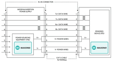
In a PoE midspan implementation, power is distributed directly through the unused Ethernet pairs. The positive PoE PSE output (V+) is connected to wires 4 and 5, while the negative PSE output (V-) is connected to wires 7 and 8. In this configuration, the power pairs are separated from the original signal pairs, which pass directly through the PoE midspan power injector. This type of implementation is shown configured using a Maxim Integrated MAX5969 single-channel PD controller and a MAX5980 four-channel PSE controller (Figure 1).
 Figure 1: A PoE midspan implementation carrying power through the formerly unused power wires in an Ethernet Cat5 cable. (Image source: Maxim Integrated)
The MAX5969 provides a complete interface for a PD complying with IEEE 802.3af/at PoE systems. The device provides the PD with a detection signature, classification signature, and an integrated isolation power switch with inrush current control. Depending on the input voltage, the MAX5969 operates in one of four different modes: PD detection; PD classification; mark event; and PD power. The device enters PD detection mode when the input voltage is between 1.4 and 10.1 volts, and PD classification mode when it is between 12.6 and 20 volts. The device enters PD power mode once the input voltage exceeds VON (35.4 volts).
The MAX5980 four-channel PSE controller is designed for use in IEEE 802.3af/at PoE PSE implementations. This device provides PD discovery, classification, current limit, and load disconnect detection, and offers four operating modes:
- Auto mode allows the device to operate automatically at its default settings without any software
- Semiautomatic mode automatically detects and classifies devices connected to the ports, but does not power a port until instructed to by software
- Manual mode allows total software control of the device and is useful for system diagnostics
- Shutdown mode terminates all activities and securely turns off power to the ports
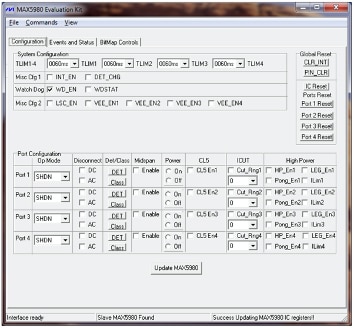
Maxim supplies the MAX5980EVKIT evaluation kit (EK) for development work with the MAX5980. The EK features an Ethernet four-port PSE circuit—comprising the MAX5980 PSE controller and four N-channel power MOSFETs—for -48 or -54 volt power supplies. The EV kit implements a separate, independent power channel for each of the four Ethernet output ports and allows the engineer to exercise the full functionality of the PSE controller for each of these channels. Configurable operational modes and high-power modes (programmable up to 30 watts per port) can be set up, and the engineer can experiment with port current information through the I2C interface, PD detection, PD classification, overcurrent and under/overvoltage protection, current foldback and DC disconnect monitoring.
Configuration can be completed via PC-compatible software, with access to each register at the bit level (Figure 2).
 Figure 2: The MAX5980 evaluation kit includes PC-compatible software which enables simple configuration of the four ports supervised by the PSE controller. (Image source: Maxim Integrated)
Adding PoE-based LED lighting
Apart from eliminating the need to install new smart light wiring, the key advantage of PoE-connected lighting is the reduction in complexity of the LED luminaire’s power supply.
LED luminaires connected to PoE sockets act as PDs, drawing clean, regulated DC power directly from the network without requiring a primary power regulation stage to convert from AC to DC and step-down the mains voltage. However, PoE’s (nominal) 44 volt DC supply is unsuitable to directly power the LEDs so an LED driver should be fitted between the supply and the light. The LED driver regulates the input converting it to the constant current, constant voltage needed by the LED.
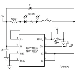
A good example of an LED driver designed for PoE operation is Maxim Integrated’s MAX16832. The device is a step-down constant-current, high-brightness LED driver featuring a voltage input range of 6.5 to 65 volts that provides a constant output current of up to 1 A with ±3% accuracy. A dedicated PWM input enables pulsed LED dimming over a wide range of brightness levels. The 2 megahertz (MHz) switching allows the use of smaller magnetic components. Efficiency is claimed to be around 95 percent when driving five LEDs in series from a 45 volt input. An analog thermal-foldback feature reduces LED current when the temperature of the LED string exceeds a specified point. A typical application circuit for the MAX16832 is shown (Figure 3).
 Figure 3: MAX16832 high-brightness LED driver application circuit. The driver is suited to PoE LED lighting applications. (Image source: Maxim Integrated)
Combining PoE-based LED lighting with Bluetooth LE
LEDs can be precisely dimmed, instantly switched on or off, and configured to give many temperature and color variations. Connectivity enables the consumer to easily access this adaptability. Using the Ethernet network directly for smart light connectivity is possible but is complicated by the fact that the network is designed to transmit large amounts of data frequently between computers rather than tiny amounts infrequently between LED lights.
In contrast, Bluetooth LE is ideally suited to the requirements of smart lighting connectivity. Key advantages include energy-efficient transfer of small amounts of data across a range of up to 100 meters (m), a broad vendor base, interoperability with smartphones—enabling configuration and control without the need for additional user interface—and mesh networking capability to support instant control of specific lights or groups of lights. (For more design information on Bluetooth mesh, see Digi-Key technical article Designing Bluetooth Low Energy Smart Applications with Bluetooth Mesh.)
Adding Bluetooth LE to a PoE LED light is not trivial (for more information on designing with Bluetooth LE, see Digi-Key technical article Bluetooth 4.1, 4.2 and 5 Compatible Bluetooth Low Energy SoCs and Tools Meet IoT Challenges), but is a worthwhile exercise for the clear advantages it brings. Additionally, developing PoE-based, wirelessly-connected smart light prototypes has been made much easier with chip vendor reference designs and evaluation kits.
One example is STMicroelectronics’ PoE reference design with Bluetooth LE connectivity, the STEVAL–POEL45W1. The reference design is based on the company’s PM8805 IEEE802.3bt-compliant PD PoE interface, an LED driver able to source up to 3 amps of current, and a Bluetooth LE module. The reference design delivers a power output of 45 watts.
The firmware offered with the reference design (STSW-POEL45FW) communicates with a PoE lighting Android application enabling management of the LED driver’s ON/OFF modes and dimming by control of the 500 hertz (Hz) pulse width modulated (PWM) duty cycle (also generated by the firmware). The designer is also free to develop application software for enhanced wireless configuration and control of the LEDs and program the Bluetooth LE chip using the company’s STSW-BNRG1STLINK utility.
ON Semiconductor’s offering is the LIGHTING-1-GEVK Connected Lighting Platform. The product comprises several plug−in evaluation boards (supporting dual LED driver, LED lighting and Bluetooth LE functionality) which can be built up into a complete commercial lighting solution with wireless connectivity. The default power supply is an AC/DC converter, but the company also provides a PoE power supply, the LIGHTING-POWER-POE-GEVB (Figure 4).
 Figure 4: ON Semiconductor’s PoE power supply for use with the company’s Connected Lighting Platform converts an LED luminaire into an IEEE 802.3af/at/bt-compliant PD. (Image source: ON Semiconductor)
The heart of the PoE power supply is the company’s NCP1096PAR2G PoE PD controller. The chip converts the LED luminaire into an IEEE 802.3af/at/bt-compliant PD. The NCP1096 supports high-power applications (up to 90 watts) through an internal pass transistor.
To use the Connected Lighting Platform with a PoE power supply requires connection of a PSE midspan power injector to the power supply’s input. ON Semiconductor recommends the Phihong POE90U-1BT-2-R, a midspan power injector offering up to 90 watts at 56 volts from a 100 volt to 240 volt input.
Once the PSE midspan power injector is plugged in to the PoE power supply input, it is simply a case of connecting the LED driver to the power supply output, the LEDs to the driver output, and the Bluetooth LE connectivity module to the connector on the LED driver for a complete PoE-based, wirelessly-connected hardware system.
Firmware development for the Connected Lighting Platform is done through the company’s Bluetooth CMSIS software development kit (SDK), a design tool that runs on a range of integrated development environments (IDEs). The firmware runs on FreeRTOS, a real-time operating system which is included as part of the CMSIS SDK. Once installed on the IDE, the SDK enables the designer to experiment with the following Bluetooth LE services:
- Light Control Service: Used by connected devices to read and change state of connected LED strings.
- Telemetry Service: Exposes variables measured by the platform to connected devices. The variables include current flowing through each LED driver and system voltage.
- PoE Power Delivery Service: Allows the peer device to retrieve information about PoE imposed power limits on the device that were negotiated between the PoE injector and platform.
The Bluetooth CMSIS SDK includes a number of sample applications which can be easily imported into the IDE workspace and from there ported to the Bluetooth LE chip in the Connected Lighting Platform (Figure 5).
 Figure 5: ON Semiconductor’s Bluetooth CMSIS SDK includes sample lighting applications for use with the company’s Connected Lighting Platform. (Image source: ON Semiconductor)
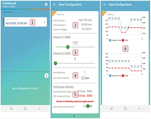
The Connected Lighting Platform is also accompanied by an associated smartphone app, the RSL10 Sense and Control App, compatible with both iOS and Android smartphones. Once downloaded to the smartphone, the app prompts the developer to pair the app with the Connected Lighting Platform. From the app, the developer can then:
- Display measured LED channel currents and system voltage telemetry data
- Independently set the PWM duty cycle of each LED channel (and therefore control dimming)
- Display information about negotiated power limits between the PoE PD controller and PSE (Figure 6)
 Figure 6: The ON Semiconductor Sense and Control App provides configuration and performance information from the Connected Lighting Platform. (Image source: ON Semiconductor)
Conclusion
Smart lighting weds efficient and long-lasting LEDs with the convenience of wireless connectivity. A simple, cost-effective alternative for upgrading existing infrastructure is to implement PoE on commercial Ethernet networks in order to power LED lights and add Bluetooth LE connectivity for wireless configuration and control of the lighting from smartphones.
While designing PoE-based, wireless smart lighting is not trivial, there are many mature PoE PSE and PD solutions, a range of PoE-compatible LED drivers, and Bluetooth LE has been designed with smart lighting in mind. Further, the development process is eased if prototype designs are based on readily available PoE plus Bluetooth LE evaluation kits and firmware examples from major chip suppliers.

Disclaimer: The opinions, beliefs, and viewpoints expressed by the various authors and/or forum participants on this website do not necessarily reflect the opinions, beliefs, and viewpoints of DigiKey or official policies of DigiKey.


