瞭解優質觸點如何增進多腳位連接器的效能
資料提供者:DigiKey 北美編輯群
2025-08-19
連接器對於系統各區塊之間,或系統與外部世界之間來說,是關鍵的機械與電氣連接介面。連接器類型的挑選需依照多種因素決定,包括電氣與機械要求、業界標準、使用與製造的簡便性、觸點的數量與類型、插拔情境、可靠度目標以及法規要求。即便如此,經典的 D-Sub 連接器主體已運用數十年,且仍是許多應用的首選連接器。
雖然連接器本體樣式和觸點排列受到廣泛關注,但觸點會大幅影響連接器的電氣與機械效能。隨著設計日益複雜且應用需求越來越高,設計人員需熟悉最新的觸點技術創新,以符合相關標準與要求,尤其是在耐用性、插入力與保持力、接觸阻抗及耐溫性方面。
本文將概述連接器的趨勢,並著重在探討 D-Sub 連接器持續發揮的作用。接著會介紹 Amphenol Positronic 的進階觸點,並說明如何利用這些觸點來增進連接器的效能。
USB、乙太網路與 D-Sub 連接器的重要性
儘管經典的 RS-232 介面已使用減少,且各種版本的 USB 及乙太網路連接器日益普及,但經典的 9引腳 D-Sub 連接器 (通常稱為DB-9) 以及更廣泛的 D-Sub 系列連接器,仍然在電子系統通訊中扮演重要角色。持續使用的原因有很多。雖然 USB 和乙太網路能符合許多互連要求,但這兩種廣泛使用的連接器類型都屬於序列式而非多線介面。可以同時傳輸數據和電力,但須對訊號類型、電壓和電流最大值以及額定功率有嚴格限制。
依照設計,USB 和乙太網路皆無法像具有多重平行觸點路徑的介面那樣,有效處理多個不相關的訊號或不同格式。另一個重要且關鍵的考量在於,標準的 USB 和乙太網路連接在設計上並無法在許多情況下達到所需的機械及電氣完整性與耐用性。
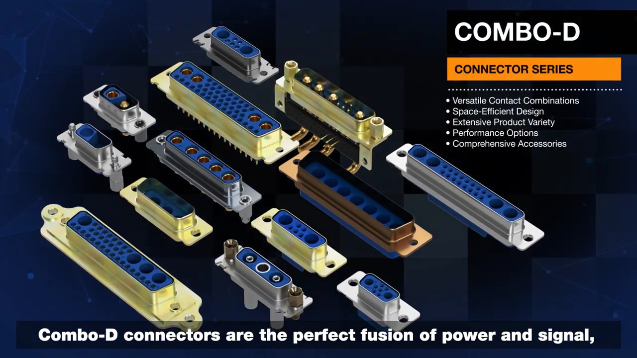
基於這些及其他原因,D-Sub 連接器仍廣泛使用。此型式自 1950 年代起就存在,並具有多項優勢。不僅全屏蔽可防電磁干擾 (EMI) 和無線射頻干擾 (RFI),更提供密封或近乎密封的外殼,因此機械結構堅固,且配對部分可用小支柱螺絲鎖緊。D-Sub 連接器主體或外殼至少提供六種標準尺寸,且在電氣觸點腳位及類型上具備彈性。除了提供所有腳位均為相同觸點類型的連接器外殼外,「Combo-D」D-Sub 連接器還可在單一連接器外殼內支援獨立訊號與電源觸點的組合 (圖 1 上)。
") 圖1:Combo-D D-Sub 連接器樣式可支援多種訊號與電源路徑的組合 (上);D-Sub連接器提供標準外殼尺寸及觸點排列 (下)。(圖片來源:Amphenol Positronic)
圖1:Combo-D D-Sub 連接器樣式可支援多種訊號與電源路徑的組合 (上);D-Sub連接器提供標準外殼尺寸及觸點排列 (下)。(圖片來源:Amphenol Positronic)
單一 D-Sub 連接器可支援多種標準混搭配置 (圖 1 下)。有雙排標準密度版本及三排高密度版本可供選擇。有供訊號、電源、屏蔽、高壓、熱電偶及光纖用的觸點。
觸點技術的創新
D-Sub 連接器外殼的優點是連接器設計中的重要部分,但電氣觸點及其特性對連接器的順利組裝來說同樣重要。多年來,觸點技術在材料、設計以及電氣和機械效能方面有了許多改進。
其中包括 Amphenol Positronic 的專利 PosiBand 觸點技術 (美國專利 7,115,002 號)。PosiBand 採用與傳統設計不同的創新觸點作法,能在多項關鍵參數上提供更優異的效能表現。
PosiBand 外部壓力元件的設計可將連接的機械動作與電氣動作完全分隔 (圖 2)。壓力元件會施加一股力量,將公引腳壓向內部母腔,形成一條長線的直接電氣接觸,進而完成機械動作。介面線的長度可變,因此設計人員能將連接的介面電阻最佳化。入口處具有實心的連續環,可增強觸點的機械堅固性。
") 圖 2:PosiBand 使用專利設計將連接的機械動作與電氣動作分隔。(圖片來源:Amphenol Positronic)
圖 2:PosiBand 使用專利設計將連接的機械動作與電氣動作分隔。(圖片來源:Amphenol Positronic)
PosiBand 內的彈簧夾 (圖 3 左) 在組件中雖小,但卻是重要的零件,也是達到效能的關鍵。此彈簧回火的鈹銅合金可對公端觸點施加一般力道,有助於形成堅固可靠的接觸配對 (圖 3 右)。同時,可提供較低的平均插入力,同時符合甚至超越效能要求。
 provides a normal force across the contact area (right)") 圖 3:PosiBand 彈簧夾 (左) 可在接觸區域 (右) 上提供一般力道,能達到最大的電氣接合面接觸面積。(圖片來源:Amphenol Positronic)
圖 3:PosiBand 彈簧夾 (左) 可在接觸區域 (右) 上提供一般力道,能達到最大的電氣接合面接觸面積。(圖片來源:Amphenol Positronic)
PosiBand 的底座觸點由黃銅製成,具有優異特性,可將電線壓接到觸點上。如此一來就可消除材料退火的需求,此過程不僅會增加成本,且若在製造過程中失誤,則會導致長期問題。
PosiBand 系統與傳統觸點設計相比,亦增加了公母觸點之間的接觸面積,因此可達到更可靠的電氣完整性。若細微觀察,接觸介面中具有更多電氣路徑。接觸面積增加,可在振動期間降低不連續性的機率。
出乎意料的是,PosiBand 系統提供較大的接觸面積,卻未增加插入力;相反地,PosiBand 的設計可提供更一致的插入力數值,進而達到較低的平均插入力。
Positronic 產品名列美國國防後勤局 (DLA) 合格產品清單 (QPL) 中,這表示已符合相關要求,包括適當的產品識別、資格認證及定期驗證測試。PosiBand 已通過 SAE AS3902 與 MIL-DTL-24308 規範認證,並且符合 GSFC S-311-P4/08 與 GSFC S-311-P4/10 更嚴格的 40 g 接觸分離測試要求。
觸點尺寸與電阻
PosiBand 觸點提供標準尺寸 20 和 22。前者適用於美國線規 (AWG) 20、22 及 24 號線,後者適用於 AWG 22、24、26、28 及 30 號線。
尺寸 22 觸點的最大電阻為 0.005 Ω,而尺寸 20 觸點的最大電阻則為 0.004 Ω。因具有低接觸電阻,且因具有極小的 I2R 損耗而讓後續的自體發熱較低,因此設計人員可使用尺寸 22 和 20 的觸點進行電力傳輸。
至於觸點的熱特性,有些工程師可能未注意到,或僅在設計及連接器挑選過程的後期才納入考量。儘管如此,散熱在評估連接器及系統效能時仍是關鍵的因素之一。PosiBand 的尺寸 20 (圖 4 上) 和尺寸 22 (圖 4 下) 觸點皆已針對不同觸點配置,進行電流與溫度上升的完整特性分析。
 and size 22 (bottom) PosiBand contacts (click to enlarge)") 圖 4:在不同配置下,尺寸 20 (上) 及 22 (下) 的 PosiBand 觸點的溫升與額定電流關係。(圖片來源:Amphenol Positronic)
圖 4:在不同配置下,尺寸 20 (上) 及 22 (下) 的 PosiBand 觸點的溫升與額定電流關係。(圖片來源:Amphenol Positronic)
允許的最大電流會受到連接和觸點可承受的最高溫度所限制。
PosiBand 產品適用於實際應用
PosiBand 觸點能以單獨零件的方式提供,以便設計人員自行組裝電纜和連接器。舉例而言,FC6020D2-14 (圖 5) 就是一款尺寸 20 的銅合金機械加工插座觸點,並且壓接於電線端子上。
 圖 5:FC6020D2-14 是一款尺寸 20 的銅合金機械加工插座觸點,且壓接在電線端子上。(圖片來源:Amphenol Positronic)
此鎳鍍銅觸點具有 1.27 µm 厚的金塗層,以確保低電阻及可靠的連續性。針對這些壓接式 (非焊接) 連接,Amphenol Positronic 提供專用的壓接工具,可確保連接符合精確規格,以達到一致性與可靠性。
若設計人員需要現成的解決方案、完全組裝的連接器,如MACH-D 系列 MCD15M51R700K/AA-15 (圖 6 左) 和 CBC7W2S110000 (圖 6 右),皆能以一些常見的配置以標準品方式供應。MCD15M51R700K/AA-15 是一款 15 腳位的不鏽鋼 D-Sub 插頭連接器 (公引腳),採用相同的尺寸 20 觸點,額定電流為 17 A。專為直角電路板焊接而設計。除了直角板安裝端子外,還提供壓接、焊杯和壓合式端接選項。
 D-sub plug connector and CBC7W2S110000 (right) 7-position combo receptacle connector") 圖 6:MCD15M51R700K/AA-15 (左) 是一款 15 腳位的 D-Sub 插頭連接器 (公引腳),採用尺寸 20 觸點;CBC7W2S110000 (右) 是一款 7 腳位搭配母觸點的複合式插座連接器,具備五個尺寸 20 的 PosiBand 訊號觸點及兩個 MC/FC 4012D 電源觸點。(圖片來源:Amphenol Positronic)
圖 6:MCD15M51R700K/AA-15 (左) 是一款 15 腳位的 D-Sub 插頭連接器 (公引腳),採用尺寸 20 觸點;CBC7W2S110000 (右) 是一款 7 腳位搭配母觸點的複合式插座連接器,具備五個尺寸 20 的 PosiBand 訊號觸點及兩個 MC/FC 4012D 電源觸點。(圖片來源:Amphenol Positronic)
相比之下,CBC7W2S110000 是一款 7 腳位搭配母座的 D-Sub 複合式插座連接器。此連接器具有五個尺寸 20 的 PosiBand 訊號觸點及兩個 MC/FC 4012D 100 A 電源連接器 (亦可提供同軸電纜觸點)。其外殼為鍍鋅鋼材質,並塗有鉻酸鹽封層,以確保電氣及環境完整性。
結論
D-Sub 系列的經典多腳位平行連接器是許多應用的首選連接器。能為設計人員提供多種實體尺寸選擇,且在觸點數量和排列上有所彈性。Amphenol Positronic 創新的 PosiBand 訊號觸點搭配 D-Sub 連接器外殼,可提升可靠性與效能表現。
聲明:各作者及/或論壇參與者於本網站所發表之意見、理念和觀點,概不反映 DigiKey 的意見、理念和觀點,亦非 DigiKey 的正式原則。