Supercapacitors - Providing a Peak Power or Secondary Power Source for Your Design
資料提供者:DigiKey 歐洲編輯群
2016-05-20
For most design teams today, working on space-constrained battery-powered consumer electronics developments would be high on the list for being the most challenging. Apart from being able to implement the desired functionality within a given enclosure size, one of the most important considerations will be that of the available power budget. The balancing act between the space available for all the electronics, such as the processor, wireless connectivity and display/UI, needs to be put against the space for the battery to power everything.
For some applications, such as those found in smartphones with a camera flash feature, the peak power load is significantly higher, albeit for a short instance, than that of any other use case. Engineers facing such a challenge might consider the use of a supercapacitor, also known as an electrical double layer capacitor (EDLC), as a way of delivering the peak load requirement. Capable of storing many 100 times more than a convenient electrolytic capacitor, a supercapacitor can typically deliver up to 4 amps for 40 milliseconds. Such EDLCs are also an ideal candidate for the provision of a backup power supply to accommodate momentary interruptions of an application's primary power source. A backup power source for solid-state disk drives, memory backup, real time clock backup power and as energy storage for energy harvesting devices are all candidates for using an EDLC.
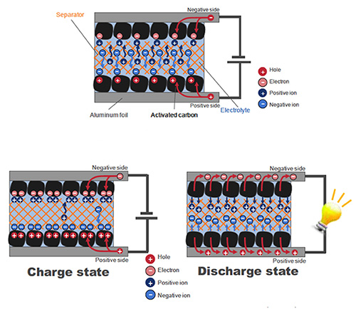
EDLCs, unlike their ceramic or electrolytic counterparts, do not utilize a dielectric layer. In its place is an electrolyte, either a solid or gel-like substance, between two electrodes (Figure 1). The resulting capacitance of this type of construction is proportional to the surface area of the electrodes and, by using powered activated carbon deposited on aluminum foil as the electrodes, provides a fairly high capacitance value. The process of ion absorption to and from the electrode surfaces creates the charge and discharge of the EDLC.

Figure 1: Construction of a supercapacitor – EDLC
The construction of EDLCs tends to vary by manufacturer, each having slightly different characteristics. For example, Murata, with its DMT/DMF series (Figure 2), uses a package of aluminum laminate film that is coated both sides by an insulating plastic layer. A sandwich of activated carbon electrodes and electrolyte makes up a multi-layered package and each sheet is separated mechanically and electrically by a separator. Also, two capacitors are formed within a single "pouch" package, and connected in series with a lead attached to the mid-point in addition to the outer electrodes. An example Murata product is the DMT334R2S47, a 470 mF supercapacitor rated at 4.2 VDC working voltage. A similar approach is used by TDK with its EDLC252520 series, an example being the EDLC252520-351-2F-21, a 350 mF with a 3.2 VDC working voltage.

Figure 2: Murata EDLC package example
By contrast, Panasonic with its Gold series of EDLCs has adopted several forms of construction that have different characteristics. A coin cell format is used for memory backup applications and a secondary power source for solar watches, a multiple stacked coin cell arrangement is used for industrial and automotive memory backup applications and, using a more familiar cylindrical package, with a relatively low ESR, is used for higher current applications such as toys. An example is the EEC-S0HD334V, a 330 mF 5.5 VDC working voltage part.
To get a better idea of an EDLC's behavior and operation it is necessary to consider its equivalent circuit model. From a simple, first look perspective, the model is as illustrated in Figure 3.

Figure 3: Simple equivalent circuit model of EDLC
Note that the combination of the two capacitor cells within the EDLC creates a further simplified model. The equivalent capacitance being half and the effective series resistance (ESR) doubled. However, this model does not take account of the actual behavior of the activated carbon electrode. Since the deposition of this results in layers, or pores, of different depths on the surface, the movement of ions varies. The result of this is that ions can move quickly to the activated carbon that is on the surface but those at a deeper level take longer. The surface accepts a charge quickly but the deeper layers take longer to full charge. In order to account for this in the equivalent circuit model, a more accurate representation – see Figure 4 – contains multiple parallel capacitors and series resistance.

Figure 4: Detailed equivalent circuit model of EDLC
Typically most manufacturers of supercapacitor EDLC devices offer devices with capacitance values ranging from a few hundreds of milliFarads up to several Farads with working voltages typically up to 5.5 VDC. While their capacitance values and their energy storage capability are high, their physical size tends to be relatively thin. For example, the Murata DMF-4B5R5G 1 F, 5.5 WVDC part measures just 1.181 x 0.515 x 0.146 inches (30.00 x 14.00 x 3.70 mm).
Compared to tantalum or aluminum capacitors, EDLCs can provide over 100 times the storage energy capability. For example, a 1.5 F 6.3 V tantalum capacitor may provide up to 20 mJ stored energy, compared to a 470 mF 4.2 V EDLC that stores 2,000 mJ of energy. Taking into account that tantalum capacitors have the reputation of catching fire should a short-circuit occur, their expense and aluminum's large dimensions and limited life-cycle, EDLCs emerge as ideal candidates for delivering high peak-load, or backup power applications, where they can deliver typically 10 Watts, and for some, up to 100 Watt output. Also, compared to using a lithium coin battery in place of an EDLC, the lithium battery is only capable of delivering very low power.
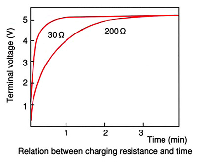
Charging an EDLC typically takes just a few minutes and will depend on the effective resistance of the device (Figure 5). Because an EDLC has many little internal resistances, the need for any external current limiting resistors is typically not required.

Figure 5: Relationship between EDLC charging - internal resistance and time
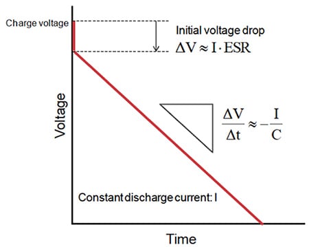
Figure 6 shows the general model for an EDLC discharge cycle based on a constant current discharge.

Figure 6: Typical discharge profile for the constant current discharge of EDLC
Figure 7 illustrates this for a Murata DMF series EDLC. There is an initial voltage drop at the moment of discharge due to the internal ESR, the drop being bigger when larger current conditions occur. The voltage of the EDLC then starts to drop with time. The speed of this drop depends on the current being consumed and the nominal capacitance value. In the case of a constant power discharge, the relationship between voltage and time is not linear and forms more of a curve based on discharge power (P), nominal capacitance (C) and the instantaneous voltage level V, calculated by dv/dt = P/CV.

Figure 7: Discharge profile of a Murata DMF EDLC
As already mentioned, there are a number of use cases that are ideal for an EDLC.
Figure 8 shows the use of an EDLC as a means of leveling out the load peaks in a battery-based design. Providing extra power to complement the battery supply output, the combined supply source meets the application needs when the load demand is more than the battery alone can provide.

Figure 8: High peak load leveling
In the use case scenario mentioned in the introduction to this article, the provision of an EDLC to provide a high peak power capability is indicated in Figure 9. Such a peak load may be that of a camera flash function on a smartphone or to accommodate a motor start peak load. By using an EDLC for these functions in place of using a higher rated battery enables design engineers to keep the overall BOM cost down and the space required to a minimum. This is especially important in today's space constrained consumer electronic devices.

Figure 9: High peak power function
An EDLC can also be used to store energy where the power source is infrequent yet a stable load condition exists. See Figure 10. The concept of using energy harvesting in place of a battery and where no other reliable power source is available is attracting those developing sensor applications for Internet of Things (IoT) applications. Energy harvested from multiple sources such as a solar cell and vibration harvester, can be easily stored in an EDLC to maintain a reliable power source for the wireless sensor application.

Figure 10: Energy storage for energy harvesting application
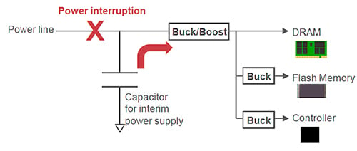
The final use case is that of providing an interim backup power supply for memory applications such as a solid-state drive (SSD) as illustrated in Figure 11. A power interruption of an SSD is a critical event. With a dependence on cache memory, should the power suddenly fail any pending disk/cache writes will be most likely lost since the correct standby/shutdown process will not have occurred. In order to prevent loss of data and potentially a corrupt disk partition, an EDLC could be used to ensure that the shutdown and/or cache write process can take place without error.

Figure 11: Backup power source for solid-state drive
EDLCs are becoming increasingly popular with design engineers as a battery and large capacitor replacement. Able to provide a high amount of energy, occupy little board space and have good levels of reliability and aging characteristics, the EDLC will be much in demand.

聲明:各作者及/或論壇參與者於本網站所發表之意見、理念和觀點,概不反映 DigiKey 的意見、理念和觀點,亦非 DigiKey 的正式原則。


