Speed Development of Secure Cellular Connected IoT Applications
資料提供者:DigiKey 北美編輯群
2018-06-26
Cellular technologies offer an increasingly attractive option for IoT connectivity thanks to emerging solutions from hardware manufacturers and cellular service providers. Even with the growing availability of cellular hardware modules, IoT development nevertheless faces significant delays as developers grapple with low-level handshaking and higher level service protocols, while also ensuring a secure implementation.
This article briefly reviews the factors behind the emergence of cellular technologies as an effective connectivity option for IoT applications, and discusses the challenges for its implementation. It then introduces a readily available cellular development platform from STMicroelectronics and shows how it can be used to address practical connectivity concerns, including high-level communications and security that are increasingly vital for IoT devices.
Wireless options for IoT
Wireless connectivity has become a fundamental requirement for many IoT applications. Although there is a wide variety of available wireless technologies, the choice of technology is typically determined largely by requirements for data rate and range (Figure 1).
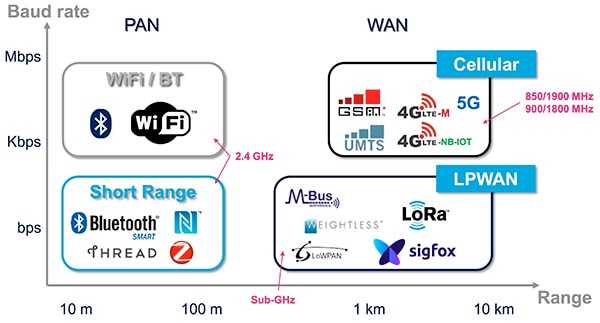
Figure 1: Cellular not only provides needed bandwidth and range, but also finds greater availability with growing coverage by LTE service providers. (Image source: STMicroelectronics)
While Bluetooth, Zigbee, and Wi-Fi continue to dominate in short-range communications, many IoT applications need to reach across significantly greater physical distances than is practical with those technologies. For these applications, emerging low-power wide-area network (LPWAN) technologies such as LoRaWAN, Sigfox, and others can meet the range requirements, but typically are unable to support higher data rates.
LTE for IoT
Commercial cellular providers have moved quickly into the IoT space with expanded LTE networks that provide bandwidth and range well beyond other commonly available wireless connectivity options. They also have the advantage of using licensed bands, which are less prone to interference. With the availability of narrowband LTE services defined in 3rd Generation Partnership Project (3GPP) LTE Release 13, cellular has become a viable option even for power-constrained devices.
While more familiar LTE services address a growing need for high bandwidth networks needed for video streaming, narrowband LTE services including LTE CAT M1 and Narrowband-IoT (NB-IoT) present more modest requirements for bandwidth and functionality. In turn, these simpler requirements enable LTE transceiver manufacturers to create solutions that meet IoT designers' need for low-power devices that are simpler to integrate in resource-constrained designs.
The combination of more effective solutions from LTE transceiver manufacturers and broader geographic availability of CAT M1 and NB-IoT services from cellular providers has turned cellular connectivity into a viable option for IoT designers. Indeed, developers can find a growing array of narrowband LTE modules such as u-blox’s SARA-R410M, or Link Labs’ LL-LTE-M-VZN-SE, that have been certified with carriers to enable rapid development of cellular connectivity for IoT devices and other connected applications. CAT M1 and NB-IoT modules such as these combine an embedded processor with a transceiver and complete RF signal path including output power amplifier (PA), input amplifier, switch, and filter (Figure 2).
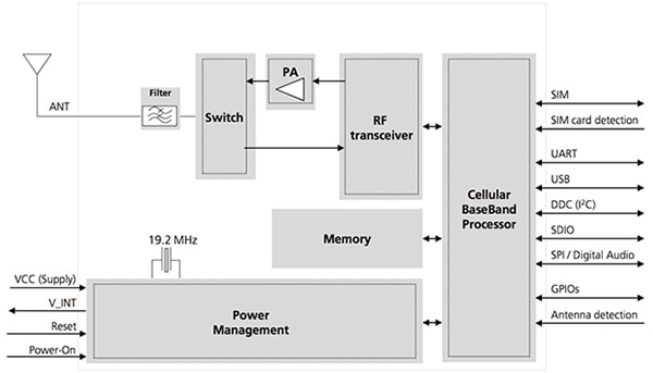
Figure 2: Advanced LTE modules such as the u-blox SARA-R410M provide a complete LTE communications subsystem that developers can integrate easily into their hardware designs using standard serial interface options. (Image source: u-blox)
For developers, integration of these highly integrated devices in custom designs is relatively straightforward at both the hardware and software levels. These modules typically support one or more standard serial interfaces, as well as support for GPIOs, antenna detection, and SIM card interface, among others. As a result, developers can quickly complete hardware integration simply by adding a suitable antenna and connecting the module to a host processor's SPI or I2C bus, or using basic UART control.
The software control requirements for these modules are just as simple. As with most transceiver modules, narrowband LTE modules respond to the same sort of AT command sequence protocol in use since the earliest days of computer modems. These LTE modules, however, provide significantly greater functionality, allowing developers to execute more complex operations with a single AT command. With u-blox’s SARA-R410M module, a developer can transmit a command such as AT+USOCO=0,"8.8.8.8", 1111 from the host to establish a peer-to-peer network connection with a remote server. In this case, the module would complete the sequence of transactions required to establish a connection identified as socket 0 to a remote host 8.8.8.8 on port 1111, automatically performing the handshake negotiation for a TCP connection.
Although the hardware and command interfaces are simple at the base level, using them in higher level communications protocols is much more complex. IoT developers can find themselves struggling to implement the high level protocols and services required in many applications. However, using STMicroelectronics’ P-L496G-CELL02 development kit and related software, developers can more rapidly deploy cellular connectivity in IoT devices.
Cellular development platform
The P-L496G-CELL02 kit provides a complete cellular IoT development platform comprising an MCU host board, LTE module expansion board, antenna, and SIM card. A member of STMicro’s Discovery board family, the host board is built around the STMicro STM32L496AGI6P MCU, and provides an on-board debugger as well as microphones, LEDs, and pushbuttons for use as basic user interface functionality.
Although the board is relatively simple, the STM32L496 MCU provides extensive functionality. Based on an Arm® Cortex®-M4 32-bit core with floating point unit (FPU), the MCU integrates 1 Mbyte of flash memory and 320 Kbytes of SRAM. This provides ample capacity for code images or even for multiple code images often used in the firmware update process. An extensive set of integrated analog and digital peripherals support a range of typical IoT application requirements for data acquisition, motor control, and more.
To meet requirements not served by the MCU itself, developers can use the host board's Arduino interface to enhance the board with functionality provided by the wide assortment of available Arduino shields. One of the emerging applications of cellular connectivity in IoT applications is its use in connecting a small network of local IoT devices to the cloud. For this usage scenario, developers can use the P-L496G-CELL02 kit as a gateway that connects to the cloud using cellular services, as well as connecting to local devices through short-range wireless connectivity options provided by Arduino shields.
For example, developers could support Wi-Fi and Bluetooth connectivity by adding Inventek Systems’ ISMART43340-C shield, or support Zigbee connectivity by adding DFRobot’s DFR0015 XBee adaptor shield and Digi International’s XBP24CZ7WIT-004 XBee module with its integrated antenna.
Of course, the critical piece in this type of cellular gateway is the cellular connectivity. With STMicro’s P-L496G-CELL02 kit, developers simply plug the LTE module expansion board into the host board's STMod+ connector to support cellular connectivity using LTE CAT M1 or LTE NB-IoT carrier services. To complement this cellular hardware platform, STMicro provides an extensive software environment that demonstrates cellular connectivity and serves as the foundation for building custom applications.
Software environment
STMicro's software environment builds on its STM32Cube software architecture, which provides application software support built on middleware components including real-time operating systems, USB support, filesystem services, and more. The middleware layer lies on top of a hardware abstraction layer (HAL) that enables portability across different STMicro MCU families. During development, developers can specify configurations using graphical wizards in STMicro's STM32CubeMX tool, which automatically generates C language initialization code.
Developers build on the baseline capabilities of the STM32Cube environment by adding extension packages that provide libraries and software samples needed to support specific areas of functionality. For IoT developers, two STM32Cube extension packages in particular support features that are important to any connected application: the STMicro X-CUBE-CLD-GEN IoT cloud software expansion, and the STMicro X-CUBE-SBSFU (Secure Boot and Secure Firmware Update) software expansion.
To support communications, the X-CUBE-CLD-GEN package adds an extensive set of middleware components, including the Eclipse Paho project's MQTT service, mbed TLS, and the lwIP TCP/IP stack (Figure 3). The extension package also provides sample applications that demonstrate use of MQTT and HTTP protocols in connecting to IoT cloud platforms including Eclipse Mosquitto, Litmus Automation, and Ubidots.
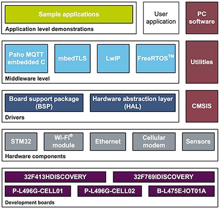
Figure 3: The ST X-CUBE-CLD-GEN IoT cloud software package extends the baseline STM32Cube environment with middleware components for cloud connectivity and sample applications demonstrating their use. (Image source: STMicroelectronics)
Included in the X-CUBE-CLD-GEN distribution, an MQTT sample application, GenericMQTTXcubeSample.c, provides a detailed example of the code required to implement MQTT-based cloud connectivity. Along with various helper functions, the module demonstrates the software design patterns required to open an MQTT connection, build a message, and publish the message to an MQTT server (Listing 1).
Copy
        network.my_socket = socket;
        network.mqttread = (network_read);
        network.mqttwrite = (network_write);

        MQTTClientInit(&client, &network, MQTT_CMD_TIMEOUT,
           mqtt_send_buffer, MQTT_SEND_BUFFER_SIZE,
           mqtt_read_buffer, MQTT_READ_BUFFER_SIZE);

        /* MQTT connect */
        MQTTPacket_connectData options = MQTTPacket_connectData_initializer;

        options.clientID.cstring = device_config->MQClientId;
        options.username.cstring = device_config->MQUserName;
        options.password.cstring = device_config->MQUserPwd;

        ret = MQTTConnect(&client, &options);
        if (ret != 0)
        {
          msg_error("MQTTConnect() failed: %d\n", ret);
        }
        else
        {
          g_connection_needed_score = 0;
          b_mqtt_connected = true;
#ifdef LITMUS_LOOP
          snprintf(mqtt_subtopic, MQTT_TOPIC_BUFFER_SIZE, "loop/req/%s/json", device_config->LoopTopicId);
#elif defined(UBIDOTS_MQTT)
          snprintf(mqtt_subtopic, MQTT_TOPIC_BUFFER_SIZE, "/v1.6/devices/%s/ts/lv", device_config->MQClientId); /* Subscribe the timestamp latest value */
#else
          snprintf(mqtt_subtopic, MQTT_TOPIC_BUFFER_SIZE, "/devices/%s/control", device_config->MQClientId);
#endif /* LITMUS_LOOP */

          ret = MQTTSubscribe(&client, mqtt_subtopic, QOS0, (allpurposeMessageHandler));
        }
    .
    .
    .
        if ( (ret < 0) || (ret >= MQTT_MSG_BUFFER_SIZE) )
        {
          msg_error("Telemetry message formatting error.\n");
        }
        else
        {
          ret = stiot_publish(&client, mqtt_pubtopic, mqtt_msg);
          if (ret == MQSUCCESS)
          {
            /* Visual notification of the telemetry publication: LED blink. */
             Led_Blink(80, 40, 5);
             /* Restore the LED state */
             Led_SetState(status_data.LedOn);
             msg_info("#\n");
             msg_info("publication topic: %s \tpayload: %s\n", mqtt_pubtopic, mqtt_msg);
          }
          else
          {
            msg_error("Telemetry publication failed.\n");
            g_connection_needed_score++;
          }
        }
Listing 1: The ST X-CUBE-CLD-GEN IoT cloud extension provides sample code and full source code such as this snippet demonstrating MQTT setup and message publishing to different MQTT services such as Litmus Automation shown here. (Code source: STMicroelectronics)
STMicro makes it even easier to set up a basic MQTT-based network. The P-L496G-CELL02 kit comes with an EMnify cellular SIM card and a free three month subscription to the EMnify network. Using this SIM card, developers can connect CELL02 kits to their own virtual private networks (VPNs) connected through the EMnify network to application servers. Here, data exchanges can occur directly between connected devices and an application server through an OpenVPN tunnel using a VPN gateway running on a lab computer in a development environment, or on a host in a public network in a production environment (Figure 4). By configuring the VPN gateway to redirect the traffic, these connections can proceed directly between application server and device without the need for network address translation (NAT).
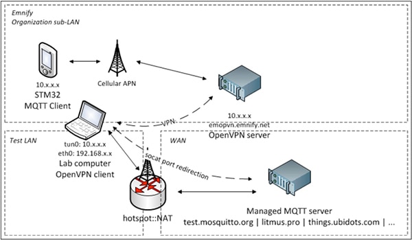
Figure 4: Developers can use the P-L496G-CELL02 kit and ST X-CUBE-CLD-GEN IoT cloud software to quickly create virtual private networks through the EMnify network to connect IoT devices and a host. (Image source: STMicroelectronics)
While the X-CUBE-CLD-GEN extension addresses the fundamental requirement for cloud connectivity in IoT devices, the X-CUBE-SBSFU software expansion mitigates a common source of threats associated with cloud connectivity. The STMicro X-CUBE-SBSFU extension provides the secure firmware update and secure boot capabilities needed to thwart attacks meant to replace device firmware with compromised code that can turn an IoT device into an instrument for further attacks on IoT networks and applications.
Along with sample applications, the X-CUBE-SBSFU package extends the STM32Cube environment with two additional middleware components – a secure engine and cryptographic library (Figure 5). The secure engine component provides services for working with protected code and data, while the cryptographic library provides a software-based asymmetric and symmetric crypto mechanism for firmware verification and decryption.
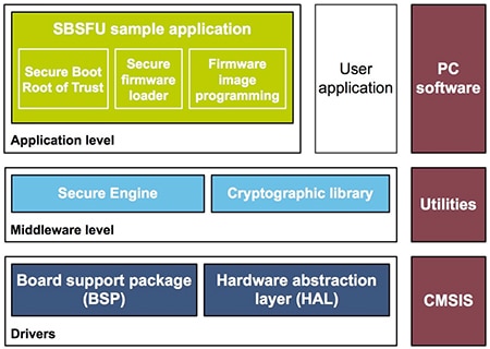
Figure 5: The ST X-CUBE-SBSFU (Secure Boot and Secure Firmware Update) software package extends the baseline STM32Cube environment with middleware components and sample applications that can provide immediate support for secure firmware update and secure boot in IoT applications. (Image source: STMicroelectronics)
In most systems, software-based crypto can provide an attack surface to hackers able to penetrate the underlying mechanisms. As a result, security specialists typically recommend use of hardware-based mechanisms for security. With the STMicro X-CUBE-SBSFU package, however, these software-based mechanisms lie protected behind fundamental hardware-based security features built into the MCU hardware.
The STM32L496 MCU features multiple hardware-based memory protection mechanisms starting with its memory protection unit (MPU), allowing developers to designate different access rights for separate regions of flash memory and SRAM. For example, SBSFU code configures the MPU to ensure that no code from other memory regions is executed while SBSFU code is being executed. After executing code for firmware verification or secure boot loading, for example, the SBSFU extension reconfigures the MPU to allow user applications to execute normally.
Besides its MPU functionality, the STM32L496 MCU provides a write protection mechanism to protect trusted code from modification from either external or internal sources, including accidental or intentional attempts to run code. In addition, the STM32L496 MCU proprietary code readout protection (PCRP) mechanism allows developers to define an area of flash memory as “execute only”. This PCRP mechanism ensures that this “execute only” area of code cannot be accessed through normal read and write operations.
As a further security measure, the STM32L496 MCU includes a built-in firewall mechanism that protects trusted code and data from any access by code outside of the firewall. Access through the firewall to protected areas can only occur through a single call gate, which is a single entry point placed at the second word of a code segment's base address. The call gate mechanism provides the sole means for accessing protected code and data, and any attempt to access protected memory other than through the call gate results in a system reset.
The SBSFU extension uses these hardware mechanisms to deliver software-based middleware able to reliably ensure firmware verification and secure boot. For example, to load secret keys required for crypto authentication mechanisms, SBSFU code uses the call gate function to open the firewall and run PCRP protected execute-only code that moves the secret key from flash to a protected SRAM region for use by the library's crypto algorithms (Figure 6).

Figure 6: To load protected SRAM with secret keys used for crypto operations, SBSFU code uses the secure engine (SE) call gate mechanism (1) to access protected functions (2) that move the secret keys to protected SRAM (3). (Image source: STMicroelectronics)
Developers use the SBSFU secure engine (SE) application programming interface (API) to activate these same hardware-based security mechanisms for accessing protected code and data. The SE interface is essentially a wrapper for this call gate mechanism, providing a relatively simple mechanism for implementing security features in an application. To access protected flash memory, the user application calls the SE interface, which ensures the proper sequence of operations for using the call gate, accessing the secure engine, cleaning up the stack, and restoring the firewall (Figure 7). The developer’s only responsibility is to ensure that they have disabled interrupts before entering this protected enclave and re-enabled interrupts on exit.
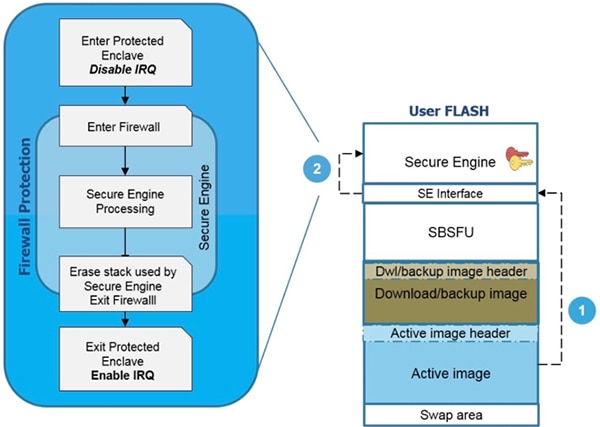
Figure 7: To implement custom secure software features, developers can use the SBSFU secure engine (SE) API, which hides the complexity of the call gate mechanism used to pass through the MCU firewall to access secure code and data. (Image source: STMicroelectronics)
Developers can examine X-CUBE-SBSFU documentation and source code to find key design patterns, including the basic approach for using the call gate mechanism. Any call to protected memory regions begins with a call to the SE interface SET_CALLGATE() function, which sets the pointer to the CallGate function, followed by a call to SE_EnterSecureMode() to disable system interrupts. From this point, subsequent calls to the SE interface use the call gate pointer to access protected code and data (Listing 2). Finally, the call sequences end with a call to SE_ExitSecureMode(), which at a minimum enables system interrupts.
Copy
void SE_SVC_Handler(uint32_t *args)
{
  /* Set the CallGate function pointer */
  SET_CALLGATE();

  /*Enter Secure Mode*/
  SE_EnterSecureMode();

  switch (args[1]) /* main case for short operations that can be done under interrupts */
  {
    /* no extra parameters calls */
    case SE_LOCK_RESTRICT_SERVICES:
      *((SE_ErrorStatus *)args[0]) = (*SE_CallGatePtr)((SE_FunctionIDTypeDef)args[1],
                                                       (SE_StatusTypeDef *)args[2]);
      break;

    /* one extra parameters calls */
    case SE_BOOT_INFO_READ_ALL_ID:
    case SE_BOOT_INFO_WRITE_ALL_ID:
    case SE_CRYPTO_HL_AUTHENTICATE_METADATA:
    case SE_CRYPTO_LL_ENCRYPT_INIT_ID:
    case SE_CRYPTO_LL_DECRYPT_INIT_ID:
    case SE_CRYPTO_LL_AUTHENTICATE_FW_INIT_ID:
      *((SE_ErrorStatus *)args[0]) = (*SE_CallGatePtr)((SE_FunctionIDTypeDef)args[1],
                                                       (SE_StatusTypeDef *)args[2],
                                                       (((uint32_t *)args[3])[0]));
      .
      .
      .

    /* four extra parameters calls */
    case SE_CRYPTO_LL_ENCRYPT_APPEND_ID:
    case SE_CRYPTO_LL_DECRYPT_APPEND_ID:
    case SE_CRYPTO_LL_AUTHENTICATE_FW_APPEND_ID:
      *((SE_ErrorStatus *)args[0]) = (*SE_CallGatePtr)((SE_FunctionIDTypeDef)args[1],
                                                       (SE_StatusTypeDef *)args[2],
                                                       (void *)(((uint32_t *)args[3])[0]),
                                                       (void *)(((uint32_t *)args[3])[1]),
                                                       (void *)(((uint32_t *)args[3])[2]),
                                                       (void *)(((uint32_t *)args[3])[3]));
      break;
    default:
      *((SE_ErrorStatus *)args[0]) = SE_ERROR;
  }
  /*Exit Secure Mode*/
  SE_ExitSecureMode();
  /*
   * End of the privileged operation execution: switching to unprivileged mode automatically.
   */
}
Listing 2: The ST X-CUBE-SBSFU includes sample applications and full source code such as this snippet demonstrating the basic design pattern associated with use of the call gate mechanism to access protected code and data. (Code source: STMicroelectronics)
Beyond these low-level mechanisms, the X-CUBE-SBSFU includes higher level functionality designed to simplify implementation of secure firmware update and secure boot. Developers can use these same code patterns to implement custom authentication and crypto features using SE API functions such as SE_CRYPTO_Encrypt_Init, SE_CRYPTO_Decrypt_Init, and SE_CRYPTO_AuthenticateFW_Init and related functions.
Conclusion
LTE cellular technology is rapidly emerging as a preferred option for long range, high availability IoT connectivity. Although advanced LTE modules have simplified hardware design, implementation of higher level functionality remains a challenge. Using the ST P-L496G-CELL02 LTE cellular development kit and accompanying software, developers can quickly take advantage of narrowband LTE connectivity for secure IoT networking applications.

聲明:各作者及/或論壇參與者於本網站所發表之意見、理念和觀點,概不反映 DigiKey 的意見、理念和觀點,亦非 DigiKey 的正式原則。


