Safely Test Line-Powered Switched Mode Power Supplies
資料提供者:DigiKey 北美編輯群
2018-03-01
Switched mode power conversion, be it in power supplies, industrial controllers, DC-DC converters, DC-AC inverters, or UPSs, offers high efficiency, small size, and light weight. However, testing or troubleshooting line-powered switched mode power supplies poses several difficult, safety-related challenges, requiring a designer to take certain precautions.
The difficulties arise from having to deal with high voltages, high temperatures, line isolation, minimum loading requirements, and voltage measurements with extreme dynamic range. This article will describe what’s needed to set up a safe test station, including devices to provide input power control, line isolation, wide dynamic range voltage measurements, and programmable load control.
SMPS test safety concerns
Switched mode power supplies (SMPSs) switch high voltages on and off with minimum transition times to reduce power losses. A typical line-powered SMPS presents several safety-related concerns (Figure 1).

Figure 1: In a typical flyback topology SMPS, the differential between the high and low voltage rails can be over 670 volts. (Image source: DigiKey)
This is a line-powered power supply utilizing flyback topology. The primary side of the circuit, shown in the yellow highlight, full wave rectifies the line (mains) input and applies it to the primary rails. This means that the voltage levels occurring between the high and low voltage rails are about 340 volts for a 120 volt line, and over 670 volts for a 240 volt line. Technicians and engineers used to voltages below 15 volts may need to be reminded that these voltages are potentially lethal and that care must be taken when working on these devices.
This rectified line voltage is stored on the primary storage capacitor, C2. This means that even if the supply is disconnected from the line, the stored charge on the storage capacitor is still dangerous. Before troubleshooting, the supply should be disconnected from the line, and the main storage capacitor should be carefully discharged through a resistor.
The switching FET, Q2, switches between the high and low rail voltages. Even while operating at high efficiency, this transistor will get quite hot and is generally mounted on a heat sink. Test operators should be cautious around the heat sinks to prevent being burned.
Note that the primary and secondary sections of the supply are electrically isolated by the flyback transformer, L2, and the optically isolated coupler, Q4. While the secondary section is connected to ground at the negative (-) output terminal, the primary is un-grounded. This condition becomes problematic when employing grounded input instruments such as oscilloscopes for troubleshooting. Connecting the ground connection of a scope probe to the components in the primary side of the supply may result in a short circuit with attendant damage to the primary components as well as the oscilloscope.
An SMPS typically requires some minimum loading in order to operate; if it’s not loaded properly, it will generally just shut down.
Finally, in light of the high voltages used, failure modes are often spectacular. For instance, a short-circuited bridge rectifier (D1-D4) might apply line voltage to the main storage capacitor, resulting in the capacitor venting its dielectric through the relief vents, or even exploding outright. So, there is the possibility of ejecta when bringing up an SMPS.
A safe SMPS test setup
An SMPS test set should employ several commonly available devices to minimize safety concerns (Figure 2).

Figure 2: A SMPS test setup employs an isolation transformer, autotransformer, safety enclosure, and a load. (Image source: DigiKey)
The purpose of the isolation transformer is to electrically isolate the primary section of the SMPS. Once isolated, it is possible to connect the ground side of a probe anywhere in the primary circuit. This will eliminate the possibility of shorting the primary. An isolation transformer such as the Bel Signal Transformer model DU-2 has both dual primary and secondary windings and can be wired for 120 volt or 240 volt nominal inputs. It can supply 9 amperes (A) at 240 volts, or 18 A at 120 volts (2 kVA). Isolation transformers with power ratings of up to 10 kVA are common.
The autotransformer is used to bring the line voltage applied to the device under test up slowly. This is done while monitoring the input current, allowing defective components to be detected before a catastrophic failure. The Staco Energy Products model 3PN1010B is a typical autotransformer that can supply up to 10 A at 0 to 140 volts (1.4 kVa). Note that an autotransformer does not provide line isolation and must be used with an isolation transformer to accomplish that.
As mentioned, a load is necessary to test an SMPS. Non-inductive resistors are often used, but note that resistive load banks also can get very hot and should be protected from accidental contact. Electronic loads are an alternative, replacing fixed resistor load banks with variable loads. The ability to control the load is very important when running tests like load regulation and output current fold-back. Programmability is a particularly important consideration if testing is to be automated.
The B&K Precision model 8514 is a representative electronic load rated at 1200 W that can be programmed via USB to operate in constant current, voltage, resistance or power mode with input voltages from 0.1 to 120 V. Electronic loads can also simulate dynamic loads that change over time.
The safety enclosure on the 8514 provides a physical barrier between the device under test and the test operator. In the event of explosive failure, it protects nearby operators. It may also include a provision to cool the device under test and the resistive load bank if one is used. Fixtures such as this generally offer quick connect and disconnect of the device under test.
Line isolation
A single-phase AC line has a hot and a neutral lead. The neutral lead is tied to ground in the distribution system but may still be several volts above ground at the power supply. The result is that there is no ground reference on the primary section of the supply. Connecting a grounded oscilloscope probe to any point in the primary circuit can result in a short circuit.
Many technicians and engineers attempt to solve this problem by removing the ground connections from the oscilloscope and ‘floating’ the scope. This is an extremely dangerous practice because it could leave the oscilloscope case at several hundred volts above ground. Anyone touching the scope case could be electrocuted.
An alternative to floating the scope is to use an isolation transformer, wired as shown in Figure 2. This separates the supply being tested from the AC line. After the isolation transformer, a ground connection can be made anywhere in the primary circuit and that point will be the ground reference.
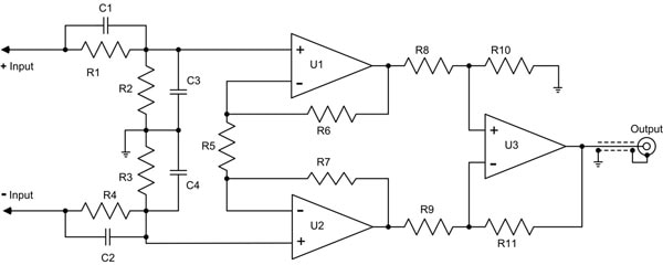
While voltage measurements can be made using this technique, a better practice is to use a differential probe designed for high-voltage measurements. Differential probes have two inputs (neither of which is grounded) and measure the difference in the voltage between the inputs. It does this by subtracting the voltage at one input from the other (Figure 3).

Figure 3: A conceptual schematic diagram of a differential probe shows the probe output is the difference between the + and - inputs. (Image source: DigiKey)
The difference measurement of the differential probe attenuates any voltage signal common to both inputs (referred to as common-mode signals). The amount of attenuation of common-mode signals is a figure of merit for a differential probe and is called the common mode rejection ratio, or CMRR, expressed in decibels (dB).
High-voltage differential probes use high attenuation ahead of matched differential inputs to measure high voltages. In Figure 3 again, the resistors R1 and R2 form one compensated attenuator, while resistors R3 and R4 form the other. The outputs from the attenuators are applied to the inputs of a three operational amplifier difference amplifier. Very careful matching of the components and a symmetrical PCB layout result in very practical levels of CMRR.
CMRR is important because voltage measurements in an SMPS can require high dynamic range. The primary side of the power supply is switching voltages of 340 volts, with relatively fast transition times. These signals radiate throughout the device. Consider trying to measure the gate drive signal on the power FET. This signal, less than 10 volts, would be difficult to see in the presence of these high-voltage common-mode signals. Using a differential probe with high CMRR rejects the interfering signals.
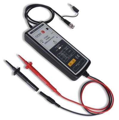
Probes such as the Cal Test Electronics model CT3681 incorporate X100 or X1000 user-selectable attenuation (Figure 4). They have a maximum voltage rating of 700 V (X100) or 7 kV (X1000), with a CMRR of -80 dB at 50 Hz, and -60 dB at 20 kHz, and a bandwidth of 70 MHz. This probe has the advantage of using a standard BNC connector at the output, rather than a proprietary probe interface, making it compatible with all oscilloscopes.

Figure 4: The Cal Test Electronics Model CT3681 70 MHz, high-voltage differential probe. This probe offers two ranges, supporting both 700 volts and 7000 volts maximum input voltages. It has a CMRR of -80 dB at 50 Hz and -60 dB at 20 kHz. (Image source: Cal Test Electronics)
Conclusion
While popular and useful, line-powered SMPSs do present safety concerns when it comes to testing them. However as shown, some solid engineering practices coupled with the use of commonly available components such as isolation transformers, autotransformers, electronic loads and differential probes, greatly reduces those risks.

聲明:各作者及/或論壇參與者於本網站所發表之意見、理念和觀點,概不反映 DigiKey 的意見、理念和觀點,亦非 DigiKey 的正式原則。


