

Fundamentals of Current Measurement: Part 3 – Funnel Amplifiers
資料提供者:DigiKey 北美編輯群
2019-01-23
Editor’s Note: Current sensing is a critical function in electronic systems but comes with complexities that are often underestimated. Part 1 of this three-part series discussed current sense resistors. Part 2 discussed the design and use of amplifiers to boost the voltage developed across current sense resistors to usable levels. Here, Part 3 discusses the use of funnel amplifiers to amplify current measurements in applications where the load is being driven by higher voltages.
Accurately measuring current flow is not nearly as easy as measuring voltage and is even more difficult when trying to measure the current flowing through a load connected to relatively high-power supply voltages. Current sense resistors, also called shunt resistors, are the technology of choice for measuring current flow due to their high measurement accuracy, low temperature coefficient, and relatively low cost. Because of their low impedance, the small voltage across the shunt resistor usually must be boosted. This task is frequently performed by a current sense amplifier connected in either a low side or high side configuration.
However, when the load is being driven by relatively high voltage power sources, such as in industrial control applications, the sense resistor can be significantly larger without depriving the load of too much drive voltage. These increased resistances produce much larger current sense voltages compared to the voltages generated by sense currents flowing through low impedance shunt resistors with values that are usually measured in milliohms or micro-ohms. These sense voltages can often be as large as several volts in high power industrial applications, which range from motor control to power conversion.
Such sense voltages often need attenuation and level shifting before they can be applied to an analog-to-digital converter (ADC), typically operating from a unipolar 3 volt or 5 volt power supply. The attenuating and level shifting signal conditioning chain is sometimes called a funnel signal chain because the sensed voltage signal narrows as it makes its way through the signal conditioning chain to the ADC. A conventional approach to reducing or funneling these sense voltages is to use passive attenuation, but a differential funnel amplifier offers an alternative that improves the measurement’s precision while reducing component count.
A funnel amplifier may perform as many as three signal conditioning tasks:
- It attenuates the sensed voltage to levels acceptable to the ADC at the end of the analog front-end (AFE) signal chain.
- It performs level translation (level shifting) if needed, such as in high side sensing designs.
- It may have differential outputs that are needed to drive fully differential ADCs.
For designers needing to measure small signals riding on extremely high common-mode voltages on the order of hundreds of volts, see “Measure Small Signals Riding on High Voltages, and Avoid Sensor Ground Loops” by Art Pini.
Review of high side and low side sensing
The most common signal chain configuration for monitoring current flow, as shown in Figure 1, includes the shunt resistor, an AFE, an ADC, and a system controller. An operational amplifier or dedicated current sense amplifier converts the small differential voltage developed across the shunt resistor to a larger output voltage required by the ADC.

Figure 1: The easiest way to measure current flow is with a current shunt resistor (far left), which develops a voltage across itself that’s proportional to the current flowing through it. A sense amplifier conditions the signal and matches it to the ADC’s input requirements. (Image source: Steve Leibson)
A low side current measurement places the current shunt resistor between the active load and ground. Low side current measurements are simpler to implement because the sense voltage across the shunt resistor is ground referenced. However, the low side measurement configuration has a significant disadvantage: the current shunt resistor sits between the load and ground, which means the load is not ground referenced. In addition, leakage currents through sneak paths from the load to ground cannot be sensed.
A high side current measurement inserts the current shunt resistor between the power source and the active load. Figure 2 illustrates circuits for making low side and high side current measurements.

Figure 2: A low side current measurement circuit places the current sense resistor between the active load and ground while a high side measurement circuit places the current sense resistor between the power source and the load. (Image source: Steve Leibson)
High side current measurements have two key advantages over low side measurements:
- It’s easy to detect a short circuit originating from within the load to ground through a sneak path because the resulting short circuit current will flow through the current shunt resistor and develop a sense voltage across it.
- High side current measurements are not ground referenced, so differential ground voltages caused by high currents flowing through the system’s ground plane won’t affect the measurement.
High side current measurements also have one significant disadvantage: the sense voltage sits atop a relatively large common-mode voltage.
For both low side and high side measurements, loads operating from high voltages and with high currents can easily generate sense voltages that exceed the input voltage ratings and even the power supply rails of the ADCs used to convert the sense voltages into digital values. In such cases, some sort of attenuation is required. Additionally, the sense voltage rides on a large voltage offset for high side measurements, often as much as tens or even hundreds of volts. Level translation is required in these situations to bring the sense voltage within range of the ADC’s input voltage rating.
Funnel amplifiers incorporate internal, factory trimmed, highly matched resistors to set precise voltage gains and offsets. These internal resistors provide better performance and better precision than designs based on discrete, unmatched resistors while reducing parts count. Finally, high performance ADCs used in these current sensing applications may have differential inputs, so some funnel amplifiers have differential outputs to properly drive these differential ADCs.
A tale of two funnel amplifiers
Analog Devices’ LT1997 funnel amplifiers – the LT1997-2 and LT1997-3 – and Analog Devices’ AD8475 fully differential funnel amplifier, are all examples with fully integrated, precision resistors. All three devices are designed to perform similar signal conditioning tasks, but all three also have very different features.
Analog Devices’ two LT1997 gain selectable funnel amplifiers are both attenuating (funnel) difference amplifiers that can translate large differential signals to a lower voltage range compatible with ADC inputs. Both LT1997 devices combine a precision operational amplifier (op amp) with a highly matched set of internal resistors on one chip. These devices can attenuate and level shift voltages accurately without the need for additional external components. Figure 3 is an internal diagram showing the components of an LT1997-2 amplifier in a DFN package, and Figure 4 is the internal diagram for an LT1997-3 amplifier in an MSOP package.

Figure 3: The LT1997-2 amplifier contains a number of precisely matched resistors that can be combined to produce several highly accurate fractional gains and attenuations. (Image source: Analog Devices)

Figure 4: The LT1997-3 amplifier contains a number of precisely matched resistors that can be combined to produce several highly accurate fractional gains and attenuations. (Image source: Analog Devices)
Note that the architectures of these two devices are quite similar, but the resistor values differ significantly even though the part numbers are very similar. Also note that the MSOP package splits the internal resistor connected to the REF pin in the DFN package into two larger resistors connected to pins REF1 and REF2.
When wired in parallel the resistance is equivalent in either package, but this feature of the MSOP package permits the two resistors to be connected to the power supply rails to establish a precise midpoint voltage reference at the internal amplifier’s positive input with no additional components. This split resistor configuration appears in both the LT1997-2 and LT1997-3 MSOP packages.
The LT1997’s internal input resistors can be wired to produce a wide range of amplifier gains. For funneling tasks, it’s possible to wire the input resistors to produce many attenuation settings that produce a funnel amplifier. Table 1 lists the 38 fractional attenuation settings that are possible using the LT1997-2 amplifier’s internal positive input resistors, while Table 2 lists the 30 settings possible with the LT1997-3’s internal positive input resistors.
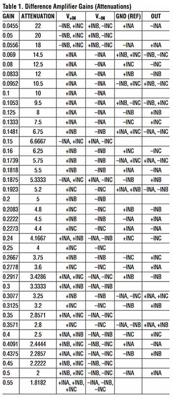
Table 1: The LT1997-2 amplifier’s precisely matched positive input resistors can be combined to produce many highly accurate fractional attenuation levels. (Table source: Analog Devices)

Table 2: The LT1997-3 amplifier’s precisely matched positive input resistors can be combined to produce many highly accurate fractional attenuation levels. (Table source: Analog Devices)
Tables 1 and 2 illustrate the many precise attenuations possible using just the built-in resistors of the LT1997-2 and LT1997-3 funnel amplifiers, but that’s not the entire story. The other internal resistors can also be used to program amplifier gain. The output of the amplifier will then be the product of the attenuation multiplied by the gain. Of course, it’s also possible to add external precision resistors to the circuit if none of the attenuation/gain combinations made possible by the internal resistors suits the overall design requirements. However, using external, discrete resistors lacks the advantage of the internal resistors’ close factory matching.
The LT1997-2 and LT1997-3 funnel amplifiers can operate across a very wide input common-mode voltage range, as high as 76 volts above the devices’ negative power rail. By using the devices’ internal input resistors in a voltage divider configuration, the analog INA inputs of the LT1997-3 can be driven safely by voltages as high as ±160 volts, and the INA inputs of the LT1997-2 can be driven by voltages as high as ±255 volts.
The close internal resistor matching results in high common-mode rejection ratios for both devices. This extreme ability to accommodate signals with very large common-mode voltages is based on a capability that Analog Devices calls “Over-The-Top” operation. This tolerates extreme common-mode voltages by trading off other specifications including linearity, input bias current, input offset current, differential input impedance, noise, and bandwidth when the device is in Over-The-Top mode. That may seem like a lot of parameters to trade off, but the benefit is the ability to handle input voltages that would be lethal to other op amps.
Both the LT1997-2 and LT1997-3 amplifiers have full data sheet specifications for operation with 5 volt single-ended and ±15 volt power supplies, but they will also operate over a wider supply voltage range of 3.3 to 50 volts. Finally, note that the LT1997 amplifiers have single-ended outputs.
A fully differential funnel amplifier
Analog Devices’ AD8475 fully differential funnel amplifier provides precision attenuation by 0.4 or 0.8, common-mode level shifting, and conversion from single-ended to differential signals with input overvoltage protection (Figure 5). The device contains a complete set of AFE building blocks, including matched, laser trimmed input resistors and a precision differential amplifier. The amplifier can be used for interfacing industrial level signals to the differential inputs of low voltage, high performance 16- or 18-bit, single supply SAR (successive approximation) ADCs. The AD8475 amplifier can process ±10 volt signals using a single power supply, and it provides overvoltage protection from input voltages as large as ±15 volts while operating on a single 5 volt power supply.

Figure 5: Analog Devices’ AD8475 fully differential funnel amplifier provides pin programmable gains of 0.8 and 0.4 using internal, matched, laser trimmed resistors. (Image source: Analog Devices)
The AD8475 comes with two standard gain options: 0.4 and 0.8. The gain of the part is set using the input pin corresponding to the desired gain.
The AD8475 funnel amplifier’s high current, differential output stage allows the amplifier to drive the switched capacitor front-end circuits of many ADCs with minimal error. In addition, the slew enhanced AD8475’s high-speed outputs allow it to settle to 18-bit precision, permitting acquisition rates as fast as 4 megasamples/second. This makes high speed current (and therefore power) measurements possible. The amplifier’s differential output easily drives the inputs of SAR, ΣΔ, and pipeline ADCs.
An AD8475 amplifier driving the differential inputs to Analog Devices’ 18-bit, 1 megasample/second, low-power AD7982 ADC is shown in Figure 6.

Figure 6: The differential outputs of the AD8575 funnel amplifier can directly drive the differential inputs of an ADC like Analog Devices’ AD7982. (Image source: Analog Devices)
This differential input ADC operates from a single power supply. The three sine waveforms illustrate this circuit performing all three signal processing tasks that a funnel amplifier might perform: attenuation, level shifting, and differential drive. Note the two sine waves in the center top and bottom of the figure, which are 180˚ out of phase. These two waveforms demonstrate the differential drive capability of the AD8475 amplifier.
The Analog Devices ADR435 ultra-low-noise XFET® voltage reference in the lower left of the figure generates a precision 5 volt reference voltage for the circuit.
The circuit in Figure 6 accommodates a bipolar ±10 volt AC input signal swing from a current sense resistor. It attenuates and level shifts the input signal, ultimately driving the ADC’s inputs with a 4 volt peak to peak signal swing centered on a 2.5 volt DC offset to match the AD7982 ADC’s input requirements. A voltage divider made from two 10 kilohm (kΩ) resistors, shown in the figure’s lower right corner, creates the 2.5 volt offset reference voltage for the AD8475’s VOCM input pin, which is used to set the amplifier’s output voltage offset. This feature permits the design engineer to dial in the exact offset voltage required by the ADC used in the design.
Conclusion
Many industrial applications drive loads with relatively high voltages. In such cases, the analog front-end for a high side current measurement circuit must accept input signal voltages that are often larger than its supply voltages. Dealing with such input voltages requires both signal attenuation and level shifting. Funnel amplifiers are purpose designed for these signal conditioning tasks by incorporating precision, factory matched, laser trimmed resistors.
Additionally, funnel amplifiers equipped with differential outputs easily drive high-speed ADCs that have switched capacitor front-end circuits with very specific drive requirements.
聲明:各作者及/或論壇參與者於本網站所發表之意見、理念和觀點,概不反映 DigiKey 的意見、理念和觀點,亦非 DigiKey 的正式原則。


