Develop the Right Power Over Ethernet System for Industrial LED Smart Lighting
資料提供者:DigiKey 北美編輯群
2018-06-11
Power over Ethernet (PoE) solves the problem of providing a convenient and practical method to supply both network connectivity and power over the same cable. However, as it evolves, designers have to wrestle with forward and backward compatibility, configuration selection, cable selection, and choosing the right interface ICs.
These ICs must not only have the core PoE functionality, but designers must look to make sure they also have the latest features to ensure safe power delivery.
With regard to compatibility, whether upgrading an existing Ethernet wired network, or designing a new PoE system, the designer needs to choose between one of the two existing standards, 802.3af or 802.3at, or the draft standard 802.3bt. While the standard selected can be based upon the project budget and amount of power needed, it’s always wise to design with future capability requirements in mind, while ensuring it’s backward compatible.
The designer also needs to decide which PoE configuration is appropriate for the target system. Configuration options may be limited when adding PoE to an existing network that uses older Ethernet cabling.
The choice of standard and topology, along with the environment, also plays a key role in deciding which cabling to use. The wrong cable choice can limit the power the system can handle as well as hinder future expandability.
This article will review the basics of PoE and how it has evolved. It will then introduce solutions that designers can use to resolve many of these issues, before finishing with a PoE application using smart lighting.
The evolution of PoE
PoE simplifies connectivity by providing both power and 100/1000Base-T Ethernet communications over the same CAT5e cable. This has no effect on Ethernet twisted pair communications. For the developer this saves design time as well as the cost of additional wiring. PoE also provides the advantage of a centralized power source, allowing for easy power management for all the Ethernet nodes. This also allows for an easy to manage source of backup power for all the connected systems.
As PoE applications have expanded, the IEEE standards committee has introduced new, higher power versions, going from the original 2003 IEEE 802.3af standard of 15 watts at the port, to the 2009 802.3at standard (also called PoE plus) of 25 watts at the port. The latest update, 802.3bt PoE, is expected to be rolled out in 2018 and provides for up to 100 watts at each port.
Note that each standard maintains backward compatibility with previous PoE standards. As efficiency is critical, the PoE standards also specify the amount of power allowed that can be lost in transmission along the CAT5e shielded twisted pair cable.
PoE cable considerations
For PoE, a 48 volt differential voltage is applied to the CAT5 cable. This voltage can be applied to the data pairs carrying the Ethernet data, without interfering with data communications. Alternately, CAT5e cables have two spare twisted pairs so the 48 volts can be applied to that pair, simplifying the power supply system. For factory or building applications, industrial CAT5e cables are preferred for their ability to withstand harsh environments and resistance to abuse such as slamming a door, stretching, or bending.
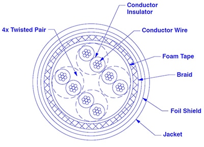
A good example of CAT5e is the ISTPHCH5MRD modular CAT5e Ethernet cable from Panduit Corp. (Figure 1). This has four twisted pairs and is designed to meet the existing IEEE 802.3af/at PoE standards, including minimizing power loss due to transmission across distance. These CAT5e cables are flame retardant, resistant to solvents, and are built to withstand twisting, pinching and other harsh abuse, making them appropriate for unforgiving industrial applications.

Figure 1: A cross-section of the Panduit ISTPHCH5MRD CAT5e industrial grade Ethernet cable shows four twisted pairs of 24 AWG copper wire. The cable is protected from pinching with heavy foam insulation tape. (Image source: Panduit Corp.)
PoE power delivery configuration
On the one end of a PoE system is the source of the Ethernet connectivity, usually either a switch or hub. At the other end, the cables terminate at the devices requiring both Ethernet connectivity and power. Each of these devices is called a Powered Device (PD).
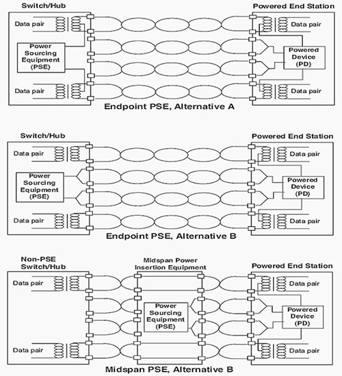
For PoE, Power Sourcing Equipment (PSE) applies the required 48 volt differential voltage to the Ethernet cable. If the PSE is located in the Ethernet switch or hub, the IEEE standard refers to this as Endpoint PSE. The IEEE standard provides for two alternate configurations for the Endpoint PSE to inject power into the cable. In Alternative A, the PSE applies a differential voltage across the two twisted pairs that carry the Ethernet data. This is the only option when using CAT5 cable with only two shielded twisted pairs.
In Alternative B, the PSE applies voltage across the two spare twisted pairs. This is the preferred method for CAT5e and later cables with four twisted pairs.
If the cable is intercepted so that the PSE injects the voltage in between the switch or hub and the PD, this is referred to as Midspan PSE. This configuration also supports having power configured according to Alternate A (power injected into the Ethernet data twisted pair) and Alternate B (power injected into the two spare twisted pairs).
PoE hardware types
These PoE injection methods are the same for the existing PoE standards 802.3af/at. The draft IEEE 802.3bt standard, when implemented, will allow power to be provided across all four twisted pairs and is compatible with 10G-Base-T (Figure 2).
PSE and PD PoE equipment are classified according to the following types:
- Type 1 uses voltage on two twisted pair, 802.3af compatible, 15 watts
- Type 2 uses voltage on two twisted pair, 802.3at compatible, 30 watts
- Type 3 uses voltage on four twisted pairs, 802.3bt draft compatible, 60 watts
- Type 4 uses voltage on four twisted pairs, 802.3bt draft compatible, 100 watts

Figure 2: The two Endpoint PSE configurations and the Midspan PSE configurations for 802.3af/at. The Endpoint PSE Alternate A is recommended for new systems using CAT5e, while the Midspan PSE can be easier for adding PoE to existing systems. Midspan PSE also supports Alternate A. (Image source: IEEE 802.3at specification)
PoE handshaking
When a PSE detects a new network connection with a PD, a short handshaking protocol is initiated between the PSE and the PD. For the PSE, this handshaking first determines if the device is indeed a PD and requires power. The PSE then needs to determine how much power the PD requires. From the PD’s perspective, this handshaking determines how much power the PSE can supply. Ultimately, handshaking allows the PSE to safely power the PD, and safely remove power if the PSE detects the PD has been disconnected.
During handshaking the PD maintains a set resistance across the PSE voltage, called a detection signature resistance, to limit the inrush current during the voltage pulse. Based on the inrush current, the PSE will classify the PD according to its power requirements as a Type 1 - 4, discussed earlier. However, when a PSE detects a new current draw on a PD, it sends a voltage pulse to the PD to determine again how much power the PD needs.
The PD interface
For developers building new PDs, the PoE interface needs to be upgradable or compatible with the new 802.3bt draft standard and still be backwards compatible to previous standards. This flexibility in the PD interface IC is critical and is provided by the TP2372 high power PoE PD Interface from Texas Instruments (Figure 3).

Figure 3: The recommended circuit for a TPS2372 in a smart lighting application, with the external resistors for configuring the MPS current (RMPS), the MPS duty cycle (RMPS_DUTY), and detection signature (RDET). (Image source: Texas Instruments)
The TP2372 is compliant with the existing IEEE 802.3bt draft standard and is also backwards compatible with 802.3af/at. An important feature of the TP2372 for engineers designing lighting PDs compatible with all PoE systems is its ability to limit the incoming current. This can be important if the PD is connected to a system where the PSE does not do any current limiting.
For example, some older, low-end Midspan PSE equipment used in some of the first PoE industrial lighting systems did not have any current limiting protection. In addition, some of the early PSEs injected voltage into the cable with no handshaking, requiring the PD to limit the current. Current limiting in the TPS2372 allows the PD to be safely connected to almost any PSE.
The TPS2372 is fully configurable using external resistors for characteristics such as MPS current and duty cycle, and PoE Type classification. Note that configuration can be set manually, or automatic settings can be enabled. The TPS2372 also handles all handshaking with the PSE, and also automatically negotiates the MPS current and duty cycle based on the type of PSE.
For ease of development, the TPS2372 is supported by TI’s TPS2372-4EVM-006 evaluation board, which supports high-power 802.3bt PoE applications, as well as the existing 802.3af/at standard.
The TPS2372-4EVM-006 evaluation board has jumpers to configure PD parameters such as the MPS duty cycle and PoE Type. It has two Ethernet connectors, the extra being for Gigabit Ethernet data pass-through.
When laying out a design using the TPS2372, it is important to minimize potential signal, EMI/ESD, and power interference. To that end:
- The power and ground traces from the RJ-45 connectors to the Ethernet transformer, TVS diode, 0.1 microFarad (µF) capacitor and CBULK, should be as short as possible and separated from the data signals.
- Use wide power traces in the power path to the device to be powered, with paired signal and return traces. Do not cross over any signals from one end of the power flow to the other.
- The TPS2372 should be laid out on the printed circuit board (pc board) over split local ground planes, with the PoE half referenced to VSS, and the converter half referenced to RTN.
- Do not route logic ground or power traces under the Ethernet input or the DC/DC converter primary.
- Separate the 48 volt input voltage and the DC/DC converter input using safe routing procedures such as specified in IEC60950. Large copper fills and traces should be used for power dissipating SMT devices and under the RJ-45 connectors.
PoE application: smart lighting
Modern buildings and factories are very focused on energy efficiency. Fluorescent tube lighting has historically been dominant in these applications, but they can be easily upgraded with high-output low-power LED lighting. LED lights have important advantages over fluorescent and incandescent lighting. Most significant is that LED lighting is much more efficient, providing more light for the given input power. LED lighting also dissipates very little heat, and LEDs do not require the ballast that florescent lighting requires.
As power consumption per fixture decreases with the use of LEDs, PoE is increasingly being used for a cabling option as it can supply enough power to drive the LED lighting, while also providing remote and Internet of Things (IoT) smart connectivity.
Smart lighting implies that lighting arrangements can be turned on and off remotely, or according to a programmed schedule, or if occupancy is detected by sensors.
In implementation, a single Ethernet endpoint may be connected to more than one lighting node. For example, a single command from the switch or hub sent to a single Ethernet-enabled device with eight lighting nodes can command the nodes to only turn on lights four and seven, and turn the other lights off.
The PoE system needs to be coupled to fixtures with appropriate LEDs in terms of output (in lumens), color temperature (in degrees Kelvin), and power consumption. LED manufacturer Wurth Electronics has a line of products that target industrial as well as indoor general lighting.
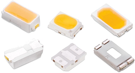
For example, the 158301250 cool white 5000K LEDs are only 3 mm x 1.4 mm, but can emit 133 lumens/watt, making them extremely efficient and particularly suited to PoE-based applications for industrial lighting. For custom lighting, multiple LEDs can be soldered onto a board according to specific system requirements.

Figure 4: The Wurth Electronics 158301250 LED is in a PLCC package and can be surface mounted in any configuration. (Image source: Wurth Electronics)
In LED PoE lighting situations it is important to not just reduce operating current at each PD, but also to reduce PoE standby current. If it is determined that the building lights at a PD must be turned off, the present PoE standards require that each PD must present to the PSE as MPS which is a current draw of 10 mA at a 20% duty cycle. The MPS tells the PSE that the PD is still connected. This results in an average MPS current consumption of 2 mA.
The new 802.3bt draft standard specifies a reduced MPS duty cycle of 1.875%, resulting in a ten times improvement of the average MPS current consumption, down to only 0.2 mA.
Conclusion
The use of PoE can greatly simplify implementing a smart lighting system in an office or industrial application. Selecting the proper cable can insure reliable power delivery, and high efficiency LEDs are available for custom lighting applications. The proper choice of parts for the PD can make the device upgradable and backwards-compatible, resulting in a safe, reliable system that can operate efficiently for years in smart network configurations.

聲明:各作者及/或論壇參與者於本網站所發表之意見、理念和觀點,概不反映 DigiKey 的意見、理念和觀點,亦非 DigiKey 的正式原則。


