Careful Sensor Selection Ensures Desirable – and Avoids Undesirable – Outcomes
資料提供者:DigiKey 北美編輯群
2016-09-08
Editor’s Note: This is part two of a series of articles (see article links below) using an example smart irrigation project to explore the types of questions and issues most real-world control systems need to address.
- Part 1 - Six Questions to Answer When Scoping an Arduino-Based Irrigation Project
- Part 2 - Careful Sensor Selection Ensures Desirable – and Avoids Undesirable – Outcomes
- Part 3 - Communication Considerations for Distributed Control Applications
A key consideration for any smart project is not just what functions the application is able to perform, but also, what fault conditions the application must accommodate, or ensure never happen. Careful selection of a group of sensors working together enables the system to overlap the sensor readings to best satisfy both sets of requirements.
In a typical irrigation system, a controller ensures a suitable actuator allows and/or prevents the flow of water from a source through piping to its destinations via sprinkler heads (Figure 1.) The primary function that any irrigation system must successfully perform is to ensure that each specific location for which it is responsible receives the prescribed volume of water. The volume of water each location or zone requires may differ, depending upon what is growing in each area. The easiest and most common way to accomplish this control is to deliver a known rate of water over a measured amount of time such that the minimum required volume of water is delivered.

Figure 1: Block diagram showing the functional areas of a typical irrigation system. Each of these areas is a potential source of faults that the controller should be able to detect. (Source: Created using DigiKey’s Scheme-it online schematic and diagramming tool)
This simple timer-based controller approach allocates the responsibility of ensuring that the rest of the irrigation system is operating correctly entirely to the user. This is an appropriate design for small-scale irrigation systems where the consequences of an undetected fault are limited. Typically, the user is responsible to make sure that:
- The controller, clock, and the watering timer schedule are operating correctly.
- The water source is providing fresh and clean water at the expected flow rate.
- The actuators continue to open and close as required.
- There are no leaks in the piping.
- All of the sprinkler heads are distributing water properly.
Smart irrigation systems can use a variety of sensors to offload some or most of the responsibility from the user to detect, respond, and notify the user when these various faults occur. The extra cost and complexity of using a smart irrigation system is justified where an undetected fault can result in significant wasted water and fines for violating local watering restrictions, either because the irrigation project is large and/or the user is not able to verify the proper operation of the system on a frequent basis. At the same time, the use of sensors provides an opportunity to save money by being able to intelligently raise and lower the volume of water delivered based on changes in the environmental conditions.
Humidity sensor
Being able to sense the humidity at each location enables the controller to intelligently adjust the volume and timing of delivering water to each location. A humidity sensor enables the controller to sense moisture and dynamically deliver the water when and where it is needed, rather than based solely on a static timetable.
Humidity is the presence of water vapor in air and the most commonly used units for measuring humidity are relative humidity, dew/frost point, and parts-per-million. Let’s clarify these terms before proceeding. Relative humidity is a function of temperature, while dew/frost point is a function of pressure – but is independent of temperature. Parts-per-million units provide an absolute measurement.
Dew/frost point measurements are often used when the dryness of the air is important, such as in industrial drying. Most humidity sensors are relative-humidity sensors and can use different sensing principles that affect which operating conditions each is best suited for.
Resistive-based humidity sensors measure changes in the resistance value of the sensor element and usually consist of a noble metal electrode on a plastic or glass cylinder. The substrate is coated with a salt or conductive polymer and when the sensor absorbs water vapor there is an increase in electrical conductivity. Resistive humidity sensors are generally field-replaceable because there is no need for humidity calibration standards. However, resistive humidity sensors do exhibit a significant temperature dependency that impacts them when installed in environments with temperature fluctuations greater than 10˚F. They also can experience a shift in their values when exposed to condensation.
Capacitive-based humidity sensors measure relative humidity and are widely used in industrial, commercial, and weather telemetry applications. These sensors rely on a hygroscopic dielectric material sandwiched between a pair of electrodes forming a small capacitor. When the sensor absorbs water vapor there is an increase in sensor capacitance. Capacitive humidity sensors are able to function at high temperatures, are able to fully recover from condensation, and have reasonable resistance to chemical vapors. However, capacitive humidity sensors are limited to a practical limit of less than ten feet between the sensing element and the signal-conditioning circuitry.
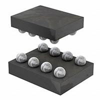
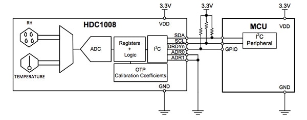
A good example of a capacitive humidity sensor is the Texas Instruments HDC1008 digital humidity sensor with integrated temperature sensor. The sensing element is placed on the bottom part of the device making it more robust in the face of dirt, dust, and other environmental contaminants (Figure 2).

Figure 2: The sensing element of the Texas Instruments HDC1008 humidity sensor is placed on the bottom part of the WLCSP to increase immunity to dirt, dust and other environmental contaminants. (Source: Texas Instruments)
The device includes an integrated resistive element that can be used to test the sensor and to drive condensation off the sensor. The humidity and temperature sensors are factory calibrated and their 16-bit registers contain a 14-bit value with an accuracy that is based on the selected conversion time (Figure 3).

Figure 3: The HDC1008 supports sleep and measurement modes. While in sleep mode, the device waits for I2C input to configure the conversion times, read the status of the battery, trigger a measurement, or read a measurement. It sets the DRDYn line low when measurement mode completes and it returns to sleep mode. (Source: Texas Instruments)
Its low power consumption, typically 110 nA of current consumption while in sleep mode, makes it suitable for battery or energy harvesting applications. The device includes BIST (built-in self-test) functionality that indicates when the voltage supply is less than 2.8 V. This lets the system notify the user when to replace the battery. Each device contains a 40-bit unique serial number.
Fault detection
While well-placed humidity sensors can enable a smart irrigation control system to avoid under- and over-watering an area, the sensors, by themselves, are not able to directly detect faults along the entire irrigation component chain. This is where incorporating additional types of sensors and cleverly correlating the data from all of these sensors can expand the range of faults that the system can detect.
A water-flow sensor enables the smart irrigation controller to detect when and how much water is flowing through the system. Combining the measurements from a flow sensor with the expected operational state enables the controller to detect system-level faults such as:
- The actuator failed to close because water is still flowing when no areas are being watered.
- There is a possible blockage in the piping or sprinkler heads because there is lower than expected water flow for the area being watered.
- There is a possible break in the piping or sprinkler heads because there is higher than expected water flow for the area being watered.
Additionally, combining multiple soil humidity readings with the water flow readings can enable the system to narrow down where breaks or blocks occur in the piping or sprinkler heads by detecting unexpected differences between current and historical readings for each individual station, as well as, detecting variances in the rate of change in humidity between each station suggesting larger or smaller flow around each humidity sensor location. The smart controller should be able to detect and recognize when the humidity at a given sensor is not increasing despite operating the watering zone for that sensor.
If the water flow reading is within expected values this could indicate that water is leaking in another area and not being delivered where it is supposed to. However, it could also mean that the humidity sensor was moved and the user failed to communicate the new location of the sensor to the controller.
Conclusion
Small and simple irrigation projects may be able to get by using only a timer to control when the system should operate. As the impact of a fault in the system increases, it can make more sense to add sensors to make sure detectable faults do not result in costly failures. Adding a humidity sensor enables the controller to avoid over- and under-watering the areas it is responsible for. Adding a water flow sensor further expands the controller’s ability to detect and possibly pinpoint the location of faults along the delivery chain of the irrigation system.
However, at the end of the day, it does not matter how much smarts are integrated into the irrigation control system if it is managing an inefficient irrigation layout, subject to poor maintenance practices, or unable to perform accurate tracking of any changes in the landscaping or environment.
Incorporating additional types of sensors along with better visibility into how the irrigation system is laid out can improve the smart irrigation controller’s water usage efficiency by being able to detect even more information about the environment and its impact on each part of the landscaping. This will be the topic of another article in this series; however, before touching on that topic, the next article in this series will address the communication considerations including intra-component communication, user interface, and extra-net communication.

聲明:各作者及/或論壇參與者於本網站所發表之意見、理念和觀點,概不反映 DigiKey 的意見、理念和觀點,亦非 DigiKey 的正式原則。


