Buck Regulators Overcome Power and Thermal Shortcomings of LDOs
資料提供者:DigiKey 北美編輯群
2025-09-23
Designers often default to low-dropout regulators (LDOs) to power industrial sensing and IoT systems utilizing 4-20 mA current loop designs. But LDOs are an increasingly inefficient fit for power-conscious and space-constrained applications. That’s why designers should consider switching to buck regulators, also known as step-down converters, especially in applications where energy efficiency, thermal performance, and extended battery life are critical.
The 4-20 mA current loop is a robust and reliable method for transmitting measurements from sensors to programmable logic controllers (PLCs) and control outputs from PLCs to process modulation devices. This system ensures accurate and noise-resistant signal transmission over long distances using twisted-pair cable, making it ideal for various industrial environments. A consistent current, regardless of wire length, has made this a standard in factory, lab, and remote-monitoring applications.
Evaluating the trade-offs between LDOs and switching regulators for current loops may help unlock smarter, more sustainable designs.
LDOs remain useful for niche cases where historically they've delivered the benefits of ultra-low noise, simplified bill of materials, or regulation with very little voltage headroom. However, they are inherently less efficient because they dissipate the difference between input and output voltage as heat. This wasted energy leads to increased thermal load in an application and can significantly reduce battery life in portable or remote applications.
When efficiency, thermal performance, or battery runtime are important, the synchronous buck is likely the superior option. A modern synchronous buck delivers 85% to 95% efficiency even at milliamp loads, drastically reduces heat, and can now provide quiescent currents in the low-µA range. While an LDO dissipates excess voltage as heat, the buck regulator efficiently converts the extra voltage into usable current, allowing more power-hungry features without overheating or wasting energy.
Those characteristics make buck regulators a go-to solution for any 4-20 mA loop that has more than a few volts of input headroom, requires thermal efficiency, or must operate for long periods on limited power, such as battery-powered sensors.
If a design has a supply voltage around 6 V higher than what the current loop's transmitter requires, and there’s space on the board for a small inductor and output capacitor, a high-efficiency synchronous buck regulator is usually the best choice. It steps down the voltage efficiently, minimizes wasted heat, and ensures enough current is available to power additional features in the 4-20 mA loop. This makes it ideal for modern transmitters that need both reliability and energy efficiency in industrial environments.
The thermal advantage of a buck regulator significantly reduces heat-sink requirements for high-current, high-temperature industrial modules. Even a 5 µA buck is still more efficient than an LDO that wastes a sizable fraction of the battery voltage as heat.
Driving the loop
The 4-20 mA current loop is one of the most common ways to send information between sensors in the field and the control systems that use their data. The signal can represent temperature, pressure, flow, or even a command to move a valve. It’s simple, reliable, and works well over long distances.
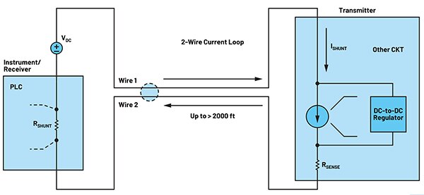
A current loop (Figure 1) can carry measurement signals from instruments (like temperature or pressure sensors) or control signals to devices that move or adjust mechanisms (like valve positioners).
Figure 1: A 4-20 mA current loop schematic illustrates how it transmits analog signals using current instead of voltage in industrial automation, sensor systems, and process control applications. (Image source: Analog Devices, Inc.)
A current loop incorporates four key elements:
- A DC power supply: Depending on the setup, this could be 9 V, 12 V, 24 V, or more. The supply must provide a little extra voltage—at least about 10% above what all the components in the loop “drop” when current flows (transmitter, receiver, wiring). Local regulators then step this down to power the sensors and electronics.
- The transmitter on the sensor side conveys electrical signals that represent the physical world: The sensor generates a raw signal on temperature, pressure, distance, or other physical measurements. If it’s an analog voltage, the transmitter’s voltage-to-current converter converts it into a proportional current between 4 mA and 20 mA. If it’s a digital sensor, the output is turned back into an analog current through a DAC. The transmitter has its own power supply, such as an LDO or buck regulator.
- A receiver on the control side: The receiver reads the 4-20 mA signal and converts it into a voltage that the control system can measure, display, or act on.
- The loop wiring connects the power supply, transmitter, and receiver in series: A loop can run for thousands of feet. In a 2-wire system, the same two wires carry both the power and the signal current. A 4-wire system uses separate pairs for power and signal.
The parts of a current loop need to be accurate, energy-efficient, and dependable, even in tough industrial environments where temperatures can swing from -40°C to +105°C. On top of that, they must also support the necessary security and system-level features that keep the loop safe and reliable.
Overcoming LDO limitations
Linear regulators are easy to use and low noise, but they waste excess energy as heat and hit a hard ceiling on available current. As designers add more features to the transmitter, such as diagnostics, digital interfaces, or local intelligence, the demand for power goes up and can exceed what a simple LDO can supply. A better option is to use a more efficient switching regulator, such as the LT8618 series from Analog Devices, Inc.
The LT8618 is a small but powerful buck converter designed for tough environments, including industrial, automotive, and other applications with unpredictable power sources. It works especially well in 4-20 mA current loop systems, offering ultralow quiescent current, high efficiency, a wide input range from 3.4 V to 60 V for continuous operation, and up to 65 V for transient conditions.
The LT8618 family offers a versatile set of buck regulators suitable for a wide range of industrial and loop-powered applications. For example:
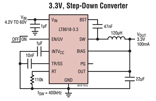
- The LT8618EDDB-3.3#TRPBF (see schematic in Figure 2) delivers a fixed 3.3 V output, ideal for designs that need a stable, well-defined voltage to handle the unpredictable rails common in industrial and field environments. With a peak output current of 100 mA, it is suitable for powering sensors, transmitters, and other supporting circuits. Ultralow quiescent current minimizes power losses during low-activity periods, helping to extend system efficiency and battery life.
Figure 2: A buck regulator configuration using the LT8618-3.3, which outputs a fixed 3.3 V. (Image source: Analog Devices, Inc.)
- The LT8618EDDB#WTRMPBF offers the same wide input range and 100 mA output, but with an adjustable output spanning 0.778 V to 40 V. This makes it suitable for powering analog, digital, or reference circuits inside a transmitter—especially when multiple supply rails are needed. Like its fixed-output counterpart, it combines fast transient response with robust short-circuit protection and thermal shutdown, ensuring dependable operation across the full -40°C to +125°C industrial range.
This flexibility allows designers to select the right regulator to match the voltage and current needs of a 4-20 mA current loop system, ensuring reliable operation while minimizing heat and wasted power.
With a low quiescent current of 2.5 µA in Burst Mode® operation, the LT8618 won’t drain loop power, leaving more available for sensors, converters, and communications. This combination of efficiency and low standby draw directly addresses the challenge of adding more functionality without overloading the current budget.
In a 4-20 mA current loop transmitter, a small inductor and output capacitor are placed near the LT8618 on the printed circuit board to form an output filter, which smooths the voltage and delivers stable power to both the sensor and supporting circuitry. A suitable input voltage, such as 24 VDC, provides ample headroom above a transmitter’s operating voltage and provides precise regulation and transient response, ensuring stable power even as the loop current shifts with changing sensor loads.
The LT8618 enables the expansion of transmitter capabilities to support advanced sensors, digital logic, and security features without exceeding the current loop’s 4-20 mA limit.
Integrated protection features, including overvoltage, thermal shutdown, and short-circuit protection, provide robust functionality in harsh field environments. The LT8618’s compact package and minimal external components simplify board layout, which is particularly crucial in space-constrained transmitters.
Conclusion
By replacing inefficient linear regulators with a compact, high-efficiency switching regulator such as the ADI LT8618, designers can overcome the limitations of LDOs and unlock new functionality while still meeting the accuracy, reliability, and temperature requirements demanded by modern industrial applications.

聲明:各作者及/或論壇參與者於本網站所發表之意見、理念和觀點,概不反映 DigiKey 的意見、理念和觀點,亦非 DigiKey 的正式原則。