Remote Control a Linear Actuator With Visuino & Arduino
2025-05-27 | By Ron Cutts
License: General Public License DC Motor Robot Accessories Arduino
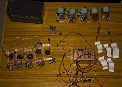
Step 1: What You Will Need


Visuino program: Download Visuino
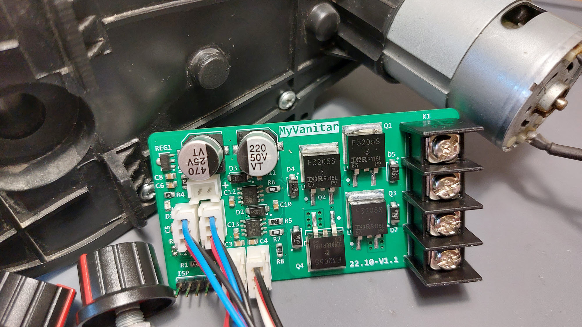
Step 2: The Circuit
Connect Remote pin [VCC] to Arduino pin [5V]
Connect Remote pin [GND] to Arduino pin [GND]
Connect Remote pin [D0] to Arduino digital pin [4]
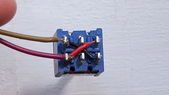
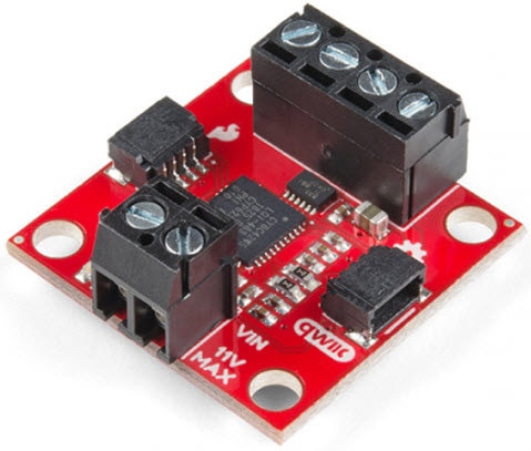
Connect Power supply (batteries) pin (gnd) to motor driver controller pin (gnd)
Connect Power supply (batteries) pin (+) to motor driver controller pin (+)
Connect Power supply (batteries) pin (+) to Arduino pin (VIN)
Connect GND from Arduino to motor driver controller pin (gnd)
Connect digital pin(6) from Arduino to motor driver pin (IN1)
Connect digital pin(8) from Arduino to motor driver pin (IN2)
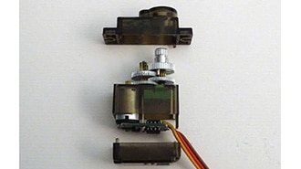
Connect Linear Actuator to the motor driver as you can see on the schematic
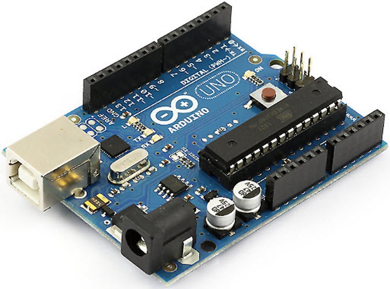
Step 3: Start Visuino, and Select the Arduino UNO Board Type


Start Visuino as shown in the first picture, Click on the "Tools" button on the Arduino component (Picture 1) in Visuino. When the dialog appears, select "Arduino UNO" as shown in Picture 2.
Step 4: In Visuino Add Components


Add 4X "Debounce Button" component
Add 2X "Digital Multi Source" component
Add "Digital (Boolean) Inverter (Not)" component
Add 3X "Digital Multi-Source Merger" component
Add 2X "Toggle(T) Flip-Flop" component
Add "Analog Value" component
Add "Speed and Direction To Speed" component
Add "Dual DC Motor Driver Digital and PWM Pins Bridge (L9110S, L298N)" component
Step 5: In Visuino Set Components


Select "MultiSource1" and in the properties window set "Output Pins" to 3
Select "MultiSource2" and in the properties window set "Output Pins" to 3
Select "DigitalMultiMerger1" and in the properties window set "Input Pins" to 3
Select "DigitalMultiMerger2" and in the properties window set "Input Pins" to 3
Select "AnalogValue1" and in the properties window set "Value" to 1
Select "DualMotorDriver1" and in the properties window
Select "Motors" > "Item[ 0 ]" > "Enabled" and click on the pin Icon and select "Boolean SinkPin"
Step 6: In Visuino Connect Components
1. Connect "DualMotorDriver1" > [Motors.Item[0].Direction] pin [Out] to "Arduino" pin Digital pin [8]
2. Connect "DualMotorDriver1" > [Motors.Item[0].Speed] pin [Out] to "Arduino" pin Digital > Analog PWM pin [6]
3. Connect "SpeedAndDirectionToSpeed1" pin [Out] to "DualMotorDriver1" > [Motors.Item[0] pin [In]
4. Connect "AnalogValue1" pin [Out] to "SpeedAndDirectionToSpeed1" pin [speed]
5. Connect "DigitalMultiMerger2" pin [Out] to "SpeedAndDirectionToSpeed1" pin [Reverse]
6. Connect "Arduino" digital pin [11] to "Button1" pin [In]
7. Connect "Button1" pin [Out] to "MultiSource1" pin [In]
8. Connect "Arduino" digital pin [12] to "Button2" pin [In]
9. Connect "Button2" pin [Out] to "MultiSource2" pin [In]
10. Connect "Arduino" digital pin [9] to "Button3" pin [In]
11. Connect "Button3" pin [Out] to "TFlipFlop1" pin [Set] and "TFlipFlop2" pin [Set]
12. Connect "Arduino" digital pin [10] to "Button4" pin [In]
13. Connect "Button4" pin [Out] to "TFlipFlop1" pin [Set] and "TFlipFlop2" pin [Reset]
14. Connect "MultiSource1" pin [0] to "DigitalMultiMerger3" pin [0]
15. Connect "MultiSource1" pin [1] to "DigitalMultiMerger2" pin [0]
16. Connect "MultiSource1" pin [2] to "DigitalMultiMerger1" pin [0]
17. Connect "MultiSource2" pin [Pin[0]] to "DigitalMultiMerger3" pin [1]
18. Connect "MultiSource2" pin [1] to "Inverter1" pin [In]
19. Connect "MultiSource2" pin [2] to "DigitalMultiMerger1" pin [1]
20. Connect "Inverter1" pin [Out] to "DigitalMultiMerger2" pin [1]
21. Connect "DigitalMultiMerger1" pin [Out] to "DualMotorDriver1" > [Motors.Item[0] pin [Enabled]
22. Connect "DigitalMultiMerger2" pin [Out] to "SpeedAndDirectionToSpeed1" pin [Reverse]
23. Connect "DigitalMultiMerger3" pin [Out] to "TFlipFlop1" pin [Reset]
24. Connect "TFlipFlop1" pin [Out] to "DigitalMultiMerger1" pin [2]
25. Connect "TFlipFlop2" pin [Out] to "DigitalMultiMerger2" pin [2]
Step 7: Generate, Compile, and Upload the Arduino Code

In Visuino, at the bottom, click on the "Build" Tab, make sure the correct port is selected, then click on the "Compile/Build and Upload" button.
Step 8: Play
If you power the Arduino module and press the buttons on the remote control, the Linear Actuator will start to move.
Congratulations! You have completed your project with Visuino. Also attached is the Visuino project that I created. You can download it here and open it in Visuino: https://www.visuino.eu