Adafruit 1.54 eInk Display Breakouts
2023-01-17 | By Adafruit Industries
License: See Original Project Displays
Courtesy of Adafruit
Guide by M. LeBlanc-Williams
Overview
Easy e-paper finally comes to microcontrollers, with these breakouts, shields, and friends that are designed to make it a breeze to add a tricolor eInk display. Chances are you've seen one of those new-fangled 'e-readers' like the Kindle or Nook. They have gigantic electronic paper 'static' displays - that means the image stays on the display even when power is completely disconnected. The image is also high contrast and very daylight readable. It really does look just like printed paper!
We've liked these displays for a long time, but they were never designed for makers to use. Finally, we decided to make our own!
We have multiple 1.54" EPD displays:
The tricolor has black and red ink pixels and a white-ish background. We have a 152x152 Tricolor display (older, lower res screen) and a 200x200 Tricolor display (newer higher res screen)
The monochrome (black and white) display has 200x200 black pixels on a white-ish background. The monochrome displays take a lot less time to update, only a couple seconds instead of 15 seconds!
Using our Arduino library, you can create a 'frame buffer' with what pixels you want to have activated and then write that out to the display. Most simple breakouts leave it at that. But if you do the math, using even the smallest 1.54" display: 152 x 152 pixels x 2 colors = 5.7 KBytes. Which won't fit into many microcontroller memories. Heck, even if you do have 32KB of RAM, why waste 6KB?
So, we did you a favor and tossed a small SRAM chip on the back. This chip shares the SPI port the eInk display uses, so you only need one extra pin. And no more frame-buffering! You can use the SRAM to set up whatever you want to display, then shuffle data from SRAM to eInk when you're ready. The library we wrote does all the work for you, you can just interface with it as if it were an Adafruit_GFX compatible display.
For ultra-low power usages, the onboard 3.3V regulator has the Enable pin brought out so you can shut down the power to the SRAM, MicroSD and display.
We even added on a MicroSD socket so you can store images, text files, whatever you like to display. Everything is 3 or 5V logic safe so you can use it with any and all microcontrollers.
Pinouts
Even though we have multiple 1.54" EPD displays, the pinouts, and dimensions are the same for all of them!
This e-Paper display uses SPI to receive image data. Since the display is SPI, it was easy to add two more SPI devices to share the bus - an SPI SRAM chip and SPI-driven SD card holder. There's quite a few pins and a variety of possible combinations for control depending on your needs.
Power Pins
3-5V / Vin - this is the power pin, connect to 3-5VDC - it has reverse polarity protection but try to wire it right!
3.3V out - this is the 3.3V output from the onboard regulator, you can 'borrow' about 100mA if you need to power some other 3.3V logic devices
GND - this is the power and signal ground pin
ENAble - this pin is all the way on the right. It is connected to the enable pin on the onboard regulator that powers everything. If you want to really have the lowest possible power draw, pull this pin low! Note that if you do so you will cut power to the eInk display but also the SPI RAM (thus erasing it) and the SD card (which means you'll have to re-initialize it when you re-power.)
Data Control Pins
SCK - this is the SPI clock input pin, required for e-Ink, SRAM and SD card
MISO - this is the SPI Microcontroller In Serial Out pin, its used for the SD card and SRAM. It isn't used for the e-Ink display which is write-only, however you'll likely be using the SRAM to buffer the display so connect this one too!
MOSI - this is the SPI Microcontroller Out Serial In pin, it is used to send data from the microcontroller to the SD card, SRAM, and e-Ink display
ECS - this is the E-Ink Chip Select, required for controlling the display
D/C - this is the e-Ink Data/Command pin, required for controlling the display
SRCS - this is the SRAM Chip Select, required for communicating with the onboard RAM chip
SDCS - this is the SD card Chip Select, required for communicating with the onboard SD card holder. You can leave this disconnected if you aren't going to access SD cards
RST - this is the E-Ink ReSeT pin, you may be able to share this with your microcontroller reset pin but if you can, connect it to a digital pin
BUSY - this is the e-Ink busy detect pin, and is optional if you don't want to connect the pin (in which case the code will just wait an approximate number of seconds)
Assembly
Assembly
Cut the header down to length if necessary. It will be easier to solder if you insert it into a breadboard - long pins down.
Add the E-Ink Display
Place the board over the pins so that the short pins poke through the top of the breakout pads.
And Solder!
Be sure to solder all pins for reliable electrical contact.
(For tips on soldering, be sure to check out the Guide to Excellent Soldering).
OK, you're done!
Wiring
Breakout Wiring
Though it looks like a lot of connections, wiring up an eInk breakout is pretty straightforward! Below shows using hardware SPI to connect it to an Adafruit Metro M4.
Vin connects to the microcontroller board's 5V or 3.3V power supply pin
GND connects to ground
CLK connects to SPI clock. It's easiest to connect it to pin 3 of the ICSP header
MOSI connects to SPI MOSI. It's easiest to connect it to pin 4 of the ICSP header
MISO connects to SPI MISO. It's easiest to connect it to pin 1 of the ICSP header
ECS connects to our e-Ink Chip Select pin. We'll be using Digital 9
D/C connects to our e-Ink data/command select pin. We'll be using Digital 10
SRCS connects to our SRAM Chip Select pin. We'll be using Digital 6
RST connects to our e-Ink reset pin. We'll be using Digital 8
BUSY connects to our e-Ink busy pin. We'll be using Digital 7
SDCS connects to our SD Card Chip Select pin. We'll be using Digital 5
Python Wiring
Raspberry Pi 3.3 to display VIN
Raspberry Pi GND to display GND
Raspberry Pi SCLK to display SCK
Raspberry Pi MOSI to display MOSI
Raspberry Pi GPIO CE0 to display ECS
Raspberry Pi GPIO 22 to display D/C
Raspberry Pi GPIO 27 to display RST
Raspberry Pi GPIO 17 to display BUSY
Usage & Expectations
One thing to remember with these small e-Ink screens is that it’s very slow compared to OLEDs, TFTs, or even 'memory displays'. It will take may seconds to fully erase and replace an image.
There's also a recommended limit on refreshing - you shouldn't refresh or change the display more than every 3 minutes (180 seconds).
You don't have to refresh often, but with tricolor displays, the larger red ink dots will slowly rise, turning the display pinkish instead of white background. To keep the background color clear and pale, refresh once a day.
Do not update more than once every 180 seconds or you may permanently damage the display.
Arduino Setup
To use the display, you will need to install the Adafruit_EPD library (code on our github repository). It is available from the Arduino library manager, so we recommend using that.
From the IDE open up the library manager...
And type in adafruit EPD to locate the library. Click Install.
If you would like to draw bitmaps, do the same with adafruit ImageReader, click Install.
Do the same to install the latest adafruit GFX library, click Install.
If using an earlier version of the Arduino IDE (pre-1.8.10), locate and install Adafruit_BusIO (newer versions handle this prerequisite automatically.)
Arduino Usage
Here is where the differences in the tricolor/monochrome and chipset/dimensions start mattering. Check carefully to make sure you are running the right example and creating the matching ThinkInk type for your display or you won’t see anything happen on the EPD (or the image may be really weird looking.)
1.54" Monochrome 200x200 Pixel Display
For the 200 x 200 monochrome display we will run a monochrome demo.
Adafruit 1.54" Monochrome eInk / ePaper Display with SRAM
Open up File→Examples→Adafruit_EPD→ThinkInk_mono
1.54" Tricolor 152x152 OR 200x200 Pixel Display
For the 152x152 OR 200x200 Tricolor display, we will run the tricolor demo.
Adafruit 1.54" 152x152 Tricolor eInk / ePaper Display with SRAM
Adafruit 1.54" Tricolor eInk / ePaper 200x200 Display with SRAM
Open up File→Examples→Adafruit_EPD→ThinkInk_tricolor
Configure Pins
No matter what display you have, you will need to verify that your pins match your wiring. At the top of the sketch find the lines that look like:
#define EPD_DC      10
#define EPD_CS      9
#define SRAM_CS     6
#define EPD_RESET   8 // can set to -1 and share with microcontroller Reset!
#define EPD_BUSY    7 // can set to -1 to not use a pin (will wait a fixed delay)
If you wired the display differently than on the wiring page, adjust the pin numbers accordingly.
Configure Display Type & Size
Find the part of the script where you can pick which display is going to be used. The eInk displays are made up a combination of a Chipset and a Film in different sizes. We have narrowed it down to just a few choices between the size of the display, chipset, and film based on available combinations. In the sketch, we have sorted it by size, so it's easy to find your display.
You will need to uncomment the appropriate initializer and leave any other type commented.
For the 1.54" 200x200 Monochrome breakout you will use ThinkInk_154_Mono_D27 display initializer.
For the 1.54" 152x152 Tricolor breakout, you will use the ThinkInk_154_Tricolor_Z17 display initializer.
For the 1.54" 200x200 Tricolor breakout, you will use the ThinkInk_154_Tricolor_Z90 display initializer.
For example, for the monochrome 200x200, uncomment this line, and comment any other line that is creating a ThinkInk display object.
// 1.54" Monochrome displays with 200x200 pixels and SSD1608 chipset
ThinkInk_154_Mono_D27 display(EPD_DC, EPD_RESET, EPD_CS, SRAM_CS, EPD_BUSY);
Upload Sketch
Go ahead and upload the sketch to your board. Once it is done uploading, open the Serial Monitor.
The display should start running a series of monochrome tests.
Arduino Bitmaps
Not only can you draw shapes, but you can also load images from the SD card, perfect for static images!
The 1.54" Monochrome display can show a max. of 200x200 pixels, and the Standard 1.54" Tri-Color display can show a max. of 152x152 pixels, and the HD Tri-Color version can show a max. of 200x200 pixels. Let's use this Blinka bitmap for our demo. Select the one that is the correct size:
Download Monochrome blinka.bmp
Download HD Tricolor blinka.bmp
Download the blinka.bmp file and place it into the base directory of a microSD card and insert it into the microSD socket in the breakout.
Plug the MicroSD card into the display. You may want to try the SD library examples before continuing, especially one that lists all the files on the SD card
Open the file→examples→Adafruit_ImageReader→ThinkInkDisplays example.
Upload to your board and you should see an image of Blinka appear.
If you want to later use your own image, use an image editing tool and crop your image to no larger than 152 pixels wide and 152 pixels high on the standard display and no larger than 200 pixels wide and 200 pixels high on the HD display. Save it as a 24-bit color BMP file - it must be 24-bit color format to work, even if it was originally a 16-bit color image - because of the way BMPs are stored and displayed!
CircuitPython Usage
Here is where the differences in the tricolor/monochrome and chipset/dimensions start mattering. Check carefully to make sure you are running the right example and creating the matching library type for your display or you won’t see anything happen on the EPD (or the image may be really weird looking.)
CircuitPython eInk displayio Library Installation
To use displayio, you will need to install the appropriate library for your display.
First make sure you are running the latest version of Adafruit CircuitPython for your board. You will need the latest version of CircuitPython.
Next, you'll need to install the necessary libraries to use the hardware--carefully follow the steps to find and install these libraries from Adafruit's CircuitPython library bundle. Our introduction guide has a great page on how to install the library bundle for both express and non-express boards.
You will need to copy the appropriate displayio driver from the bundle lib folder to a lib folder on your CIRCUITPY drive. The displayio driver contains the initialization codes specific to your display that are needed to for it to work. Since there is more than one driver, you will need to copy the correct file over. Here is a list of each of the displays and the correct driver for that display.
To use the eInk displays with displayio, you will need to use the latest version of CircuitPython and a board that can fit `displayio`. See the Support Matrix to determine if `displayio` is available on a given board: https://circuitpython.readthedocs.io/en/latest/shared-bindings/support_matrix.html
Adafruit_CircuitPython_SSD1608
The 200x200 monochrome display with SSD1608 driver uses the Adafruit_CircuitPython_SSD1608 library. Copy the adafruit_ssd1608.mpy file from the bundle to the lib folder on your CIRCUITPY drive.
Adafruit 1.54" Monochrome eInk / ePaper Display with SRAM
Adafruit_CircuitPython_IL0373
The 152x152 Tricolor display with IL0373 uses the Adafruit_CircuitPython_ILI0373 library. Copy the adafruit_il0373.mpy file from the bundle to the lib folder on your CIRCUITPY drive.
Adafruit 1.54" 152x152 Tricolor eInk / ePaper Display with SRAM
Adafruit_CircuitPython_SSD1681
The 200x200 Tricolor display with SSD1681 driver uses the Adafruit_CircuitPython_SSD1681 library. Copy the adafruit_ssd1681.mpy file from the bundle to the lib folder on your CIRCUITPY drive.
Adafruit 1.54" Tricolor eInk / ePaper 200x200 Display with SRAM
Image File
To show you how to use the eInk with displayio, we'll show you how to draw a bitmap onto it. First start by downloading display-ruler.bmp.
Copy display-ruler.bmp into the root directory of your CIRCUITPY drive.
Monochrome Display Usage
In the examples folder for your SSD1608 displayio driver, there should be a test for your display which we have listed here:
# SPDX-FileCopyrightText: 2021 ladyada for Adafruit Industries
# SPDX-License-Identifier: MIT

"""Simple test script for 1.54" 200x200 monochrome display.

Supported products:
  * Adafruit 1.54" Monochrome ePaper Display Breakout
    * https://www.adafruit.com/product/4196
  """

import time
import board
import displayio
import adafruit_ssd1608

displayio.release_displays()

# This pinout works on a Feather M4 and may need to be altered for other boards.
spi = board.SPI()  # Uses SCK and MOSI
epd_cs = board.D9
epd_dc = board.D10
epd_reset = board.D5
epd_busy = board.D6

display_bus = displayio.FourWire(
    spi, command=epd_dc, chip_select=epd_cs, reset=epd_reset, baudrate=1000000
)
time.sleep(1)

display = adafruit_ssd1608.SSD1608(
    display_bus, width=200, height=200, busy_pin=epd_busy, rotation=180
)

g = displayio.Group()

with open("/display-ruler.bmp", "rb") as f:
    pic = displayio.OnDiskBitmap(f)
    # CircuitPython 6 & 7 compatible
    t = displayio.TileGrid(
        pic, pixel_shader=getattr(pic, "pixel_shader", displayio.ColorConverter())
    )
    # CircuitPython 7 compatible only
    # t = displayio.TileGrid(pic, pixel_shader=pic.pixel_shader)
    g.append(t)

    display.show(g)

    display.refresh()

    print("refreshed")

time.sleep(120)Configure and Upload
You will want to change the epd_reset and epd_busy to the correct values. If you wired it up as shown on the Wiring page, you will want to change it to these values:
epd_reset = board.D8
epd_busy = board.D7
Save it to your CIRCUITPY drive as code.py and it should automatically run. Your display will look something like this:
Tricolor Display Usage
HD Tricolor Display
In the examples folder for your SSD1681 displayio driver, there should be a test for your display which we have listed here:
# SPDX-FileCopyrightText: 2017 Scott Shawcroft, written for Adafruit Industries
# SPDX-FileCopyrightText: Copyright (c) 2021 Melissa LeBlanc-Williams for Adafruit Industries
#
# SPDX-License-Identifier: Unlicense

"""Simple test script for 1.54" 200x200 tri-color display.
Supported products:
  * Adafruit 1.54" Tri-Color Display Breakout
    * https://www.adafruit.com/product/4868
  """

import time
import board
import displayio
import adafruit_ssd1681

displayio.release_displays()

# This pinout works on a Feather M4 and may need to be altered for other boards.
spi = board.SPI()  # Uses SCK and MOSI
epd_cs = board.D9
epd_dc = board.D10
epd_reset = board.D5
epd_busy = board.D6

display_bus = displayio.FourWire(
    spi, command=epd_dc, chip_select=epd_cs, reset=epd_reset, baudrate=1000000
)
time.sleep(1)

display = adafruit_ssd1681.SSD1681(
    display_bus,
    width=200,
    height=200,
    busy_pin=epd_busy,
    highlight_color=0xFF0000,
    rotation=180,
)

g = displayio.Group()

with open("/display-ruler.bmp", "rb") as f:
    pic = displayio.OnDiskBitmap(f)
    # CircuitPython 6 & 7 compatible
    t = displayio.TileGrid(
        pic, pixel_shader=getattr(pic, "pixel_shader", displayio.ColorConverter())
    )
    # CircuitPython 7 compatible only
    # t = displayio.TileGrid(pic, pixel_shader=pic.pixel_shader)
    g.append(t)

    display.show(g)

    display.refresh()

    print("refreshed")

time.sleep(120)Standard Tricolor Display
In the examples folder for your ILI0373 displayio driver, there should be a test for your display which we have listed here:
# SPDX-FileCopyrightText: 2021 ladyada for Adafruit Industries
# SPDX-License-Identifier: MIT

"""Simple test script for 1.54" 152x152 tri-color display.

Supported products:
  * Adafruit 1.54" Tri-Color Display Breakout
    * https://www.adafruit.com/product/3625
  """

import time
import board
import displayio
import adafruit_il0373

displayio.release_displays()

# This pinout works on a Feather M4 and may need to be altered for other boards.
spi = board.SPI()  # Uses SCK and MOSI
epd_cs = board.D9
epd_dc = board.D10
epd_reset = board.D5
epd_busy = board.D6

display_bus = displayio.FourWire(
    spi, command=epd_dc, chip_select=epd_cs, reset=epd_reset, baudrate=1000000
)
time.sleep(1)

display = adafruit_il0373.IL0373(
    display_bus,
    width=152,
    height=152,
    busy_pin=epd_busy,
    highlight_color=0xFF0000,
    rotation=180,
)

g = displayio.Group()

with open("/display-ruler.bmp", "rb") as f:
    pic = displayio.OnDiskBitmap(f)
    # CircuitPython 6 & 7 compatible
    t = displayio.TileGrid(
        pic, pixel_shader=getattr(pic, "pixel_shader", displayio.ColorConverter())
    )
    # CircuitPython 7 compatible only
    # t = displayio.TileGrid(pic, pixel_shader=pic.pixel_shader)
    g.append(t)

    display.show(g)

    display.refresh()

    print("refreshed")

time.sleep(120)Configure and Upload
For either display, you will want to change the epd_reset and epd_busy to the correct values. If you wired it up as shown on the Wiring page, you will want to change it to these values:
epd_reset = board.D8
epd_busy = board.D7
Save it to your CIRCUITPY drive as code.py and it should automatically run. Your display will look something like this:
Python Setup
It's easy to use eInk breakouts with Python and the Adafruit CircuitPython EPD library. This library allows you to easily write Python code to control the display.
Since there are dozens of Linux computers/boards you can use, we will show wiring for Raspberry Pi. For other platforms, please visit the guide for CircuitPython on Linux to see whether your platform is supported.
Note this is not a kernel driver that will let you have the console appear on the eInk. However, this is handy when you want to use the eInk display purely from 'user Python' code!
You can only use this technique with Linux/computer devices that have hardware SPI support, and not all single board computers have an SPI device, so check before continuing.
You'll need to install the Adafruit_Blinka library that provides the CircuitPython support in Python. This may also require enabling SPI on your platform and verifying you are running Python 3. Since each platform is a little different, and Linux changes often, please visit the CircuitPython on Linux guide to get your computer ready!
Python Installation of EPD Library
Once that's done, from your command line run the following command:
sudo pip3 install adafruit-circuitpython-epd
If your default Python is version 3 you may need to run 'pip' instead. Just make sure you aren't trying to use CircuitPython on Python 2.x, it isn't supported!
If that complains about pip3 not being installed, then run this first to install it:
sudo apt-get install python3-pip
Download font5x8.bin
This library also requires a font file to run! You can download it below. Before continuing, make sure the folder you are running scripts from contains the font5x8.bin file.
Alternatively, you can use wget to directly download the file to your pi:
wget https://github.com/adafruit/Adafruit_CircuitPython_framebuf/raw/main/examples/font5x8.bin
DejaVu TTF Font
Raspberry Pi usually comes with the DejaVu font already installed, but in case it didn't, you can run the following to install it:
sudo apt-get install fonts-dejavu
This package was previously calls ttf-dejavu, so if you are running an older version of Raspberry Pi OS, it may be called that.
Pillow Library
Some of the examples also use PIL, the Python Imaging Library, to allow graphics and using text with custom fonts. There are several system libraries that PIL relies on, so installing via a package manager is the easiest way to bring in everything:
sudo apt-get install python3-pil
That's it. You should be ready to go.
Python Usage
Note this is not a kernel driver that will let you have the console appear on the eInk. However, this is handy when you want to use the eInk display purely from 'user Python' code!
You can only use this technique with Linux/computer devices that have hardware SPI support, and not all single board computers have an SPI device, so check before continuing.
To demonstrate the usage of the display, we'll initialize it and draw some lines from the Python REPL.
Run the following code to import the necessary modules and set up the pin assignments. We set the SRAM CS pin to None because the Raspberry Pi has lots of RAM, so we don't really need it.
import digitalio
import busio
import board
from adafruit_epd.epd import Adafruit_EPD

spi = busio.SPI(board.SCK, MOSI=board.MOSI, MISO=board.MISO)
ecs = digitalio.DigitalInOut(board.CE0)
dc = digitalio.DigitalInOut(board.D22)
rst = digitalio.DigitalInOut(board.D27)
busy = digitalio.DigitalInOut(board.D17)
srcs = None
Depending on the exact E-Ink display you're using, the driver and object initialization will differ a bit because we have to tell Python what the chip driver is, and what the size of the display is!
Run the following code to initialize the Monochrome display:
Adafruit 1.54" Monochrome eInk / ePaper Display with SRAM
from adafruit_epd.ssd1608 import Adafruit_SSD1608

display = Adafruit_SSD1608(200, 200, spi, cs_pin=ecs, dc_pin=dc, sramcs_pin=srcs, rst_pin=rst, busy_pin=busy)
Run the following code to initialize the lower-res Tricolor display:
Adafruit 1.54" 152x152 Tricolor eInk / ePaper Display with SRAM
from adafruit_epd.il0373 import Adafruit_IL0373
display = Adafruit_IL0373(152, 152, spi, cs_pin=ecs, dc_pin=dc, sramcs_pin=srcs, rst_pin=rst, busy_pin=busy)
Run the following code to initialize the newer high-res Tricolor display:
Adafruit 1.54" Tricolor eInk / ePaper 200x200 Display with SRAM
from adafruit_epd.ssd1681 import Adafruit_SSD1681

display = Adafruit_SSD1681(200, 200, spi, cs_pin=ecs, dc_pin=dc, sramcs_pin=srcs, rst_pin=rst, busy_pin=busy)
Monochrome Example
Now we can clear the screens buffer and draw some shapes. Once we're done drawing, we need to tell the screen to update using the display() method.
display.rotation = 2
display.fill(Adafruit_EPD.WHITE)

display.fill_rect(20, 20, 50, 60, Adafruit_EPD.BLACK)
display.hline(80, 30, 60, Adafruit_EPD.BLACK)
display.vline(80, 30, 60, Adafruit_EPD.BLACK)

display.display()
Tricolor Example
The Tricolor example is almost the same as the monochrome example, except we added another color in. Once we're done drawing, we need to tell the screen to update using the display() method.
display.rotation = 2
display.fill(Adafruit_EPD.WHITE)

display.fill_rect(20, 20, 50, 60, Adafruit_EPD.RED)
display.hline(80, 30, 60, Adafruit_EPD.BLACK)
display.vline(80, 30, 60, Adafruit_EPD.BLACK)

display.display()
Your display will look something like this:
That's all there is to drawing simple shapes with eInk displays and CircuitPython!
Bitmap Example
Here's a complete example of how to display a bitmap image on your display. Note that any .bmp image you want to display must be exactly the size of your display. We will be using the image below on the 1.54" display. Click the button below to download the image and save it as blinka.bmp on your Raspberry Pi. We will be using a Tricolor bitmap, but it should still work on a monochrome display.
Click here to download blinka for the 1.54" Low Res Tricolor display
Click here to download blinka for the 1.54" High Res Tricolor and Mono displays
Save the following code to your Raspberry Pi as epd_bitmap.py.
# SPDX-FileCopyrightText: 2021 ladyada for Adafruit Industries
# SPDX-License-Identifier: MIT

import digitalio
import busio
import board
from adafruit_epd.epd import Adafruit_EPD
from adafruit_epd.il0373 import Adafruit_IL0373
from adafruit_epd.il91874 import Adafruit_IL91874  # pylint: disable=unused-import
from adafruit_epd.il0398 import Adafruit_IL0398  # pylint: disable=unused-import
from adafruit_epd.ssd1608 import Adafruit_SSD1608  # pylint: disable=unused-import
from adafruit_epd.ssd1675 import Adafruit_SSD1675  # pylint: disable=unused-import
from adafruit_epd.ssd1680 import Adafruit_SSD1680  # pylint: disable=unused-import
from adafruit_epd.ssd1681 import Adafruit_SSD1681  # pylint: disable=unused-import
from adafruit_epd.uc8151d import Adafruit_UC8151D  # pylint: disable=unused-import


# create the spi device and pins we will need
spi = busio.SPI(board.SCK, MOSI=board.MOSI, MISO=board.MISO)
ecs = digitalio.DigitalInOut(board.D10)
dc = digitalio.DigitalInOut(board.D9)
srcs = digitalio.DigitalInOut(board.D7)  # can be None to use internal memory
rst = digitalio.DigitalInOut(board.D11)  # can be None to not use this pin
busy = digitalio.DigitalInOut(board.D12)  # can be None to not use this pin

# give them all to our driver
print("Creating display")
# display = Adafruit_SSD1608(200, 200,        # 1.54" HD mono display
# display = Adafruit_SSD1675(122, 250,        # 2.13" HD mono display
# display = Adafruit_SSD1680(122, 250,        # 2.13" HD Tri-color display
# display = Adafruit_SSD1681(200, 200,        # 1.54" HD Tri-color display
# display = Adafruit_IL91874(176, 264,        # 2.7" Tri-color display
# display = Adafruit_IL0373(152, 152,         # 1.54" Tri-color display
# display = Adafruit_UC8151D(128, 296,        # 2.9" mono flexible display
# display = Adafruit_IL0373(128, 296,         # 2.9" Tri-color display
# display = Adafruit_IL0398(400, 300,         # 4.2" Tri-color display
display = Adafruit_IL0373(
    104,
    212,  # 2.13" Tri-color display
    spi,
    cs_pin=ecs,
    dc_pin=dc,
    sramcs_pin=srcs,
    rst_pin=rst,
    busy_pin=busy,
)

# IF YOU HAVE A 2.13" FLEXIBLE DISPLAY uncomment these lines!
# display.set_black_buffer(1, False)
# display.set_color_buffer(1, False)

# IF YOU HAVE A 2.9" FLEXIBLE DISPLAY uncomment these lines!
# display.set_black_buffer(1, True)
# display.set_color_buffer(1, True)

display.rotation = 0

FILENAME = "blinka.bmp"


def read_le(s):
    # as of this writting, int.from_bytes does not have LE support, DIY!
    result = 0
    shift = 0
    for byte in bytearray(s):
        result  = byte << shift
        shift  = 8
    return result


class BMPError(Exception):
    pass


def display_bitmap(epd, filename):  # pylint: disable=too-many-locals, too-many-branches
    try:
        f = open(filename, "rb")  # pylint: disable=consider-using-with
    except OSError:
        print("Couldn't open file")
        return

    print("File opened")
    try:
        if f.read(2) != b"BM":  # check signature
            raise BMPError("Not BitMap file")

        bmpFileSize = read_le(f.read(4))
        f.read(4)  # Read & ignore creator bytes

        bmpImageoffset = read_le(f.read(4))  # Start of image data
        headerSize = read_le(f.read(4))
        bmpWidth = read_le(f.read(4))
        bmpHeight = read_le(f.read(4))
        flip = True

        print(
            "Size: %d\nImage offset: %d\nHeader size: %d"
            % (bmpFileSize, bmpImageoffset, headerSize)
        )
        print("Width: %d\nHeight: %d" % (bmpWidth, bmpHeight))

        if read_le(f.read(2)) != 1:
            raise BMPError("Not singleplane")
        bmpDepth = read_le(f.read(2))  # bits per pixel
        print("Bit depth: %d" % (bmpDepth))
        if bmpDepth != 24:
            raise BMPError("Not 24-bit")
        if read_le(f.read(2)) != 0:
            raise BMPError("Compressed file")

        print("Image OK! Drawing...")

        rowSize = (bmpWidth * 3   3) & ~3  # 32-bit line boundary

        for row in range(bmpHeight):  # For each scanline...
            if flip:  # Bitmap is stored bottom-to-top order (normal BMP)
                pos = bmpImageoffset   (bmpHeight - 1 - row) * rowSize
            else:  # Bitmap is stored top-to-bottom
                pos = bmpImageoffset   row * rowSize

            # print ("seek to %d" % pos)
            f.seek(pos)
            rowdata = f.read(3 * bmpWidth)
            for col in range(bmpWidth):
                b, g, r = rowdata[3 * col : 3 * col   3]  # BMP files store RGB in BGR
                if r < 0x80 and g < 0x80 and b < 0x80:
                    epd.pixel(col, row, Adafruit_EPD.BLACK)
                elif r >= 0x80 and g >= 0x80 and b >= 0x80:
                    pass  # epd.pixel(row, col, Adafruit_EPD.WHITE)
                elif r >= 0x80:
                    epd.pixel(col, row, Adafruit_EPD.RED)
    except OSError:
        print("Couldn't read file")
    except BMPError as e:
        print("Failed to parse BMP: "   e.args[0])
    finally:
        f.close()
    print("Finished drawing")


# clear the buffer
display.fill(Adafruit_EPD.WHITE)
display_bitmap(display, FILENAME)
display.display()Before running it, we need to change a few pin definitions though. Find the section of code that looks like this:
ecs = digitalio.DigitalInOut(board.D10)
dc = digitalio.DigitalInOut(board.D9)
srcs = digitalio.DigitalInOut(board.D7)    # can be None to use internal memory
rst = digitalio.DigitalInOut(board.D11)    # can be None to not use this pin
busy = digitalio.DigitalInOut(board.D12)   # can be None to not use this pin
Change the pins to the following to match the wiring on the Raspberry Pi:
ecs = digitalio.DigitalInOut(board.CE0)
dc = digitalio.DigitalInOut(board.D22)
srcs = None
rst = digitalio.DigitalInOut(board.D27)
busy = digitalio.DigitalInOut(board.D17)
Next, find the section that looks like this:
# display = Adafruit_SSD1608(200, 200,        # 1.54" HD mono display
# display = Adafruit_SSD1675(122, 250,        # 2.13" HD mono display
# display = Adafruit_SSD1681(200, 200,        # 1.54" HD Tri-color display
# display = Adafruit_IL91874(176, 264,        # 2.7" Tri-color display
# display = Adafruit_IL0373(152, 152,         # 1.54" Tri-color display
# display = Adafruit_IL0373(128, 296,         # 2.9" Tri-color display
# display = Adafruit_IL0398(400, 300,         # 4.2" Tri-color display
display = Adafruit_IL0373(
    104,
    212,
    spi,  # 2.13" Tri-color display
    cs_pin=ecs,
    dc_pin=dc,
    sramcs_pin=srcs,
    rst_pin=rst,
    busy_pin=busy,
)
Comment out these lines:
display = Adafruit_IL0373(
    104,
    212,  # 2.13" Tri-color display
and uncomment the line that corresponds with your display.
Next, we tell the display the rotation setting we want to use. This can be a value between 0-3. For the 1.54" displays, a value of 2 seems to work well.
display.rotation = 2
Now go to the command prompt on your Raspberry Pi and run the script with the following command:
python3 epd_bitmap.py
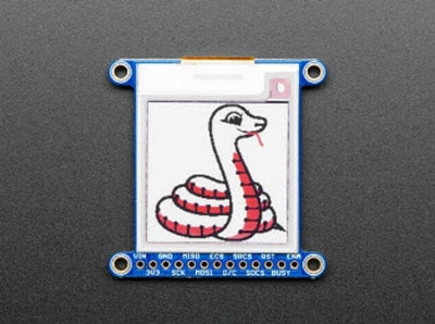
After a few seconds, your display should show an image like this:
Full Example Code
Here is the full example code.
To run the code sample below, you will need to change the pins the same way as you did in the Tricolor Bitmap Example.
# SPDX-FileCopyrightText: 2021 ladyada for Adafruit Industries
# SPDX-License-Identifier: MIT

import digitalio
import busio
import board
from adafruit_epd.epd import Adafruit_EPD
from adafruit_epd.il0373 import Adafruit_IL0373
from adafruit_epd.il91874 import Adafruit_IL91874  # pylint: disable=unused-import
from adafruit_epd.il0398 import Adafruit_IL0398  # pylint: disable=unused-import
from adafruit_epd.ssd1608 import Adafruit_SSD1608  # pylint: disable=unused-import
from adafruit_epd.ssd1675 import Adafruit_SSD1675  # pylint: disable=unused-import
from adafruit_epd.ssd1680 import Adafruit_SSD1680  # pylint: disable=unused-import
from adafruit_epd.ssd1681 import Adafruit_SSD1681  # pylint: disable=unused-import
from adafruit_epd.uc8151d import Adafruit_UC8151D  # pylint: disable=unused-import

# create the spi device and pins we will need
spi = busio.SPI(board.SCK, MOSI=board.MOSI, MISO=board.MISO)
ecs = digitalio.DigitalInOut(board.D12)
dc = digitalio.DigitalInOut(board.D11)
srcs = digitalio.DigitalInOut(board.D10)  # can be None to use internal memory
rst = digitalio.DigitalInOut(board.D9)  # can be None to not use this pin
busy = digitalio.DigitalInOut(board.D5)  # can be None to not use this pin

# give them all to our drivers
print("Creating display")
# display = Adafruit_SSD1608(200, 200,        # 1.54" HD mono display
# display = Adafruit_SSD1675(122, 250,        # 2.13" HD mono display
# display = Adafruit_SSD1680(122, 250,        # 2.13" HD Tri-color display
# display = Adafruit_SSD1681(200, 200,        # 1.54" HD Tri-color display
# display = Adafruit_IL91874(176, 264,        # 2.7" Tri-color display
# display = Adafruit_IL0373(152, 152,         # 1.54" Tri-color display
# display = Adafruit_UC8151D(128, 296,        # 2.9" mono flexible display
# display = Adafruit_IL0373(128, 296,         # 2.9" Tri-color display
# display = Adafruit_IL0398(400, 300,         # 4.2" Tri-color display
display = Adafruit_IL0373(
    104,
    212,  # 2.13" Tri-color display
    spi,
    cs_pin=ecs,
    dc_pin=dc,
    sramcs_pin=srcs,
    rst_pin=rst,
    busy_pin=busy,
)

# IF YOU HAVE A 2.13" FLEXIBLE DISPLAY uncomment these lines!
# display.set_black_buffer(1, False)
# display.set_color_buffer(1, False)

# IF YOU HAVE A 2.9" FLEXIBLE DISPLAY uncomment these lines!
# display.set_black_buffer(1, True)
# display.set_color_buffer(1, True)

display.rotation = 1

# clear the buffer
print("Clear buffer")
display.fill(Adafruit_EPD.WHITE)
display.pixel(10, 100, Adafruit_EPD.BLACK)

print("Draw Rectangles")
display.fill_rect(5, 5, 10, 10, Adafruit_EPD.RED)
display.rect(0, 0, 20, 30, Adafruit_EPD.BLACK)

print("Draw lines")
display.line(0, 0, display.width - 1, display.height - 1, Adafruit_EPD.BLACK)
display.line(0, display.height - 1, display.width - 1, 0, Adafruit_EPD.RED)

print("Draw text")
display.text("hello world", 25, 10, Adafruit_EPD.BLACK)
display.display()Image Drawing with Pillow
In this image, we will use Pillow to resize and crop the image automatically and draw it the the ePaper Display. Pillow is really powerful and with it you can open and render additional file formats such as PNG or JPG. Let's start with downloading a PNG of blinka that has been adjusted down to 3 colors, so it prints nicely on an ePaper Display. We are using PNG for this because it is a lossless format and won't introduce unexpected colors in.
Make sure you save it as blinka.png and place it in the same folder as your script. Here's the code we'll be loading onto the Raspberry Pi. Go ahead and copy it onto your Raspberry Pi and save it as epd_pillow_image.py. We'll go over the interesting parts.
# SPDX-FileCopyrightText: 2019 Melissa LeBlanc-Williams for Adafruit Industries
# SPDX-License-Identifier: MIT

"""
Image resizing and drawing using the Pillow Library. For the image, check out the
associated Adafruit Learn guide at:
https://learn.adafruit.com/adafruit-eink-display-breakouts/python-code

"""

import digitalio
import busio
import board
from PIL import Image
from adafruit_epd.il0373 import Adafruit_IL0373
from adafruit_epd.il91874 import Adafruit_IL91874  # pylint: disable=unused-import
from adafruit_epd.il0398 import Adafruit_IL0398  # pylint: disable=unused-import
from adafruit_epd.ssd1608 import Adafruit_SSD1608  # pylint: disable=unused-import
from adafruit_epd.ssd1675 import Adafruit_SSD1675  # pylint: disable=unused-import
from adafruit_epd.ssd1680 import Adafruit_SSD1680  # pylint: disable=unused-import
from adafruit_epd.ssd1681 import Adafruit_SSD1681  # pylint: disable=unused-import
from adafruit_epd.uc8151d import Adafruit_UC8151D  # pylint: disable=unused-import


# create the spi device and pins we will need
spi = busio.SPI(board.SCK, MOSI=board.MOSI, MISO=board.MISO)
ecs = digitalio.DigitalInOut(board.CE0)
dc = digitalio.DigitalInOut(board.D22)
srcs = None
rst = digitalio.DigitalInOut(board.D27)
busy = digitalio.DigitalInOut(board.D17)

# give them all to our driver
# display = Adafruit_SSD1608(200, 200,        # 1.54" HD mono display
# display = Adafruit_SSD1675(122, 250,        # 2.13" HD mono display
# display = Adafruit_SSD1680(122, 250,        # 2.13" HD Tri-color or mono display
# display = Adafruit_SSD1681(200, 200,        # 1.54" HD Tri-color display
# display = Adafruit_IL91874(176, 264,        # 2.7" Tri-color display
# display = Adafruit_IL0373(152, 152,         # 1.54" Tri-color display
# display = Adafruit_UC8151D(128, 296,        # 2.9" mono flexible display
# display = Adafruit_IL0373(128, 296,         # 2.9" Tri-color display
# display = Adafruit_IL0398(400, 300,         # 4.2" Tri-color display
display = Adafruit_IL0373(
    104,
    212,  # 2.13" Tri-color display
    spi,
    cs_pin=ecs,
    dc_pin=dc,
    sramcs_pin=srcs,
    rst_pin=rst,
    busy_pin=busy,
)

# IF YOU HAVE A 2.13" FLEXIBLE DISPLAY uncomment these lines!
# display.set_black_buffer(1, False)
# display.set_color_buffer(1, False)

# IF YOU HAVE A 2.9" FLEXIBLE DISPLAY uncomment these lines!
# display.set_black_buffer(1, True)
# display.set_color_buffer(1, True)

display.rotation = 1

image = Image.open("blinka.png")

# Scale the image to the smaller screen dimension
image_ratio = image.width / image.height
screen_ratio = display.width / display.height
if screen_ratio < image_ratio:
    scaled_width = image.width * display.height // image.height
    scaled_height = display.height
else:
    scaled_width = display.width
    scaled_height = image.height * display.width // image.width
image = image.resize((scaled_width, scaled_height), Image.BICUBIC)

# Crop and center the image
x = scaled_width // 2 - display.width // 2
y = scaled_height // 2 - display.height // 2
image = image.crop((x, y, x   display.width, y   display.height)).convert("RGB")

# Convert to Monochrome and Add dithering
# image = image.convert("1").convert("L")

# Display image.
display.image(image)
display.display()So, we start with our usual imports including a couple of Pillow modules and the ePaper display drivers.
import digitalio
import busio
import board
from PIL import Image, ImageDraw
from adafruit_epd.il0373 import Adafruit_IL0373
from adafruit_epd.il91874 import Adafruit_IL91874
from adafruit_epd.il0398 import Adafruit_IL0398
from adafruit_epd.ssd1608 import Adafruit_SSD1608
from adafruit_epd.ssd1675 import Adafruit_SSD1675
from adafruit_epd.ssd1681 import Adafruit_SSD1681
That is followed by initializing the SPI bus and defining a few pins here. The reason we chose these is because they allow you to use the same code with the EPD bonnets if you chose to do so.
spi = busio.SPI(board.SCK, MOSI=board.MOSI, MISO=board.MISO)
ecs = digitalio.DigitalInOut(board.CE0)
dc = digitalio.DigitalInOut(board.D22)
srcs = None
rst = digitalio.DigitalInOut(board.D27)
busy = digitalio.DigitalInOut(board.D17)
We wanted to make these examples work on as many displays as possible with very few changes. The 2.13" Tricolor display is selected by default. For other displays, go ahead and comment out the following lines:
display = Adafruit_IL0373(
104,
212, # 2.13" Tri-color display
and uncomment the line appropriate for your display.
#display = Adafruit_SSD1608(200, 200,        # 1.54" HD mono display
#display = Adafruit_SSD1675(122, 250,        # 2.13" HD mono display
#display = Adafruit_SSD1681(200, 200,        # 1.54" HD Tri-color display
#display = Adafruit_IL91874(176, 264,        # 2.7" Tri-color display
#display = Adafruit_IL0373(152, 152,         # 1.54" Tri-color display
#display = Adafruit_IL0373(128, 296,         # 2.9" Tri-color display
#display = Adafruit_IL0398(400, 300,         # 4.2" Tri-color display
display = Adafruit_IL0373(
    104,
    212,  # 2.13" Tri-color display
    spi,
    cs_pin=ecs,
    dc_pin=dc,
    sramcs_pin=srcs,
    rst_pin=rst,
    busy_pin=busy
)
Next change the rotation setting to 2.
display.rotation = 2
Next, we open the Blinka image, which we've named blinka.png, which assumes it is in the same directory that you are running the script from. Feel free to change it if it doesn't match your configuration.
image = Image.open("blinka.png")Here's where it starts to get interesting. We want to scale the image so that it matches either the width or height of the display, depending on which is smaller, so that we have some of the image to chop off when we crop it. So, we start by calculating the width to height ration of both the display and the image. If the height is the closer of the dimensions, we want to match the image height to the display height and let it be a bit wider than the display. Otherwise, we want to do the opposite.
Once we've figured out how we're going to scale it, we pass in the new dimensions and using a Bicubic rescaling method, we reassign the newly rescaled image back to image. Pillow has quite a few different methods to choose from, but Bicubic does a great job and is reasonably fast.
Nearest actually gives a little better result with the Tricolor eInks, but loses detail with displaying a color image on the monochrome display, so we decided to go with the best balance.
image_ratio = image.width / image.height
screen_ratio = display.width / display.height
if screen_ratio < image_ratio:
    scaled_width = image.width * display.height // image.height
    scaled_height = display.height
else:
    scaled_width = display.width
    scaled_height = image.height * display.width // image.width
image = image.resize((scaled_width, scaled_height), Image.BICUBIC)
Next, we want to figure the starting x and y points of the image where we want to begin cropping it so that it ends up centered. We do that by using a standard centering function, which is basically requesting the difference of the center of the display and the center of the image. Just like with scaling, we replace the image variable with the newly cropped image.
x = scaled_width // 2 - display.width // 2
y = scaled_height // 2 - display.height // 2
image = image.crop((x, y, x   display.width, y   display.height))
Finally, we take our image, draw it to the frame buffer and display it. At this point, the image should have the exact same dimensions at the display and fill it completely.
display.image(image)
display.display()
Now go to the command prompt on your Raspberry Pi and run the script with the following command:
python3 epd_pillow_image.py
After a few seconds, your display should show this image:
Drawing Shapes and Text with Pillow
In the next example, we'll take a look at drawing shapes and text. This is very similar to the displayio example, but it uses Pillow instead. Go ahead and copy it onto your Raspberry Pi and save it as epd_pillow_demo.py. Here's the code for that.
# SPDX-FileCopyrightText: 2019 Melissa LeBlanc-Williams for Adafruit Industries
# SPDX-License-Identifier: MIT

"""
ePaper Display Shapes and Text demo using the Pillow Library.

"""

import digitalio
import busio
import board
from PIL import Image, ImageDraw, ImageFont
from adafruit_epd.il0373 import Adafruit_IL0373
from adafruit_epd.il91874 import Adafruit_IL91874  # pylint: disable=unused-import
from adafruit_epd.il0398 import Adafruit_IL0398  # pylint: disable=unused-import
from adafruit_epd.ssd1608 import Adafruit_SSD1608  # pylint: disable=unused-import
from adafruit_epd.ssd1675 import Adafruit_SSD1675  # pylint: disable=unused-import
from adafruit_epd.ssd1680 import Adafruit_SSD1680  # pylint: disable=unused-import
from adafruit_epd.ssd1681 import Adafruit_SSD1681  # pylint: disable=unused-import
from adafruit_epd.uc8151d import Adafruit_UC8151D  # pylint: disable=unused-import

# First define some color constants
WHITE = (0xFF, 0xFF, 0xFF)
BLACK = (0x00, 0x00, 0x00)
RED = (0xFF, 0x00, 0x00)

# Next define some constants to allow easy resizing of shapes and colors
BORDER = 20
FONTSIZE = 24
BACKGROUND_COLOR = BLACK
FOREGROUND_COLOR = WHITE
TEXT_COLOR = RED

# create the spi device and pins we will need
spi = busio.SPI(board.SCK, MOSI=board.MOSI, MISO=board.MISO)
ecs = digitalio.DigitalInOut(board.CE0)
dc = digitalio.DigitalInOut(board.D22)
srcs = None
rst = digitalio.DigitalInOut(board.D27)
busy = digitalio.DigitalInOut(board.D17)

# give them all to our driver
# display = Adafruit_SSD1608(200, 200,        # 1.54" HD mono display
# display = Adafruit_SSD1675(122, 250,        # 2.13" HD mono display
# display = Adafruit_SSD1680(122, 250,        # 2.13" HD Tri-color or mono display
# display = Adafruit_SSD1681(200, 200,        # 1.54" HD Tri-color display
# display = Adafruit_IL91874(176, 264,        # 2.7" Tri-color display
# display = Adafruit_IL0373(152, 152,         # 1.54" Tri-color display
# display = Adafruit_UC8151D(128, 296,        # 2.9" mono flexible display
# display = Adafruit_IL0373(128, 296,         # 2.9" Tri-color display
# display = Adafruit_IL0398(400, 300,         # 4.2" Tri-color display
display = Adafruit_IL0373(
    104,
    212,  # 2.13" Tri-color display
    spi,
    cs_pin=ecs,
    dc_pin=dc,
    sramcs_pin=srcs,
    rst_pin=rst,
    busy_pin=busy,
)

# IF YOU HAVE A 2.13" FLEXIBLE DISPLAY uncomment these lines!
# display.set_black_buffer(1, False)
# display.set_color_buffer(1, False)

# IF YOU HAVE A 2.9" FLEXIBLE DISPLAY uncomment these lines!
# display.set_black_buffer(1, True)
# display.set_color_buffer(1, True)

display.rotation = 1

image = Image.new("RGB", (display.width, display.height))

# Get drawing object to draw on image.
draw = ImageDraw.Draw(image)

# Draw a filled box as the background
draw.rectangle((0, 0, display.width - 1, display.height - 1), fill=BACKGROUND_COLOR)

# Draw a smaller inner foreground rectangle
draw.rectangle(
    (BORDER, BORDER, display.width - BORDER - 1, display.height - BORDER - 1),
    fill=FOREGROUND_COLOR,
)

# Load a TTF Font
font = ImageFont.truetype("/usr/share/fonts/truetype/dejavu/DejaVuSans.ttf", FONTSIZE)

# Draw Some Text
text = "Hello World!"
(font_width, font_height) = font.getsize(text)
draw.text(
    (display.width // 2 - font_width // 2, display.height // 2 - font_height // 2),
    text,
    font=font,
    fill=TEXT_COLOR,
)

# Display image.
display.image(image)
display.display()Just like in the last example, we'll do our imports, but this time we're including the ImageDraw and ImageFont Pillow modules because we'll be drawing some text this time.
import digitalio
import busio
import board
from PIL import Image, ImageDraw, ImageFont
from adafruit_epd.il0373 import Adafruit_IL0373
from adafruit_epd.il91874 import Adafruit_IL91874
from adafruit_epd.il0398 import Adafruit_IL0398
from adafruit_epd.ssd1608 import Adafruit_SSD1608
from adafruit_epd.ssd1675 import Adafruit_SSD1675
from adafruit_epd.ssd1681 import Adafruit_SSD1681
Next, we define some colors that can be used with Pillow.
WHITE = (0xFF, 0xFF, 0xFF)
BLACK = (0x00, 0x00, 0x00)
RED = (0xFF, 0x00, 0x00)
After that, we create some parameters that are easy to change. If you had a smaller display for instance, you could reduce the FONTSIZE and BORDER parameters. The BORDER will be the size in pixels of the green border between the edge of the display and the inner purple rectangle. The FONTSIZE will be the size of the font in points so that we can adjust it easily for different displays. You could play around with the colors as well. One thing to note is that on monochrome displays, the RED will show up as BLACK.
For the 1.54" display, a BORDER value of 10 and a FONTSIZE value of 20 looks good.
BORDER = 10
FONTSIZE = 20
BACKGROUND_COLOR = BLACK
FOREGROUND_COLOR = WHITE
TEXT_COLOR = RED
After that, the initializer and rotation sections are exactly the same as in the previous example. If you have are using a different display than the 2.13" Tricolor, go ahead and adjust your initializer as explained in the previous example. After that, we will create an image with our dimensions and use that to create a draw object. The draw object will have all of our drawing functions.
image = Image.new('RGB', (display.width, display.height))

draw = ImageDraw.Draw(image)
Next, we clear whatever is on the screen by drawing a rectangle using the BACKGROUND_COLOR that takes up the full screen.
draw.rectangle((0, 0, display.width, display.height), fill=BACKGROUND_COLOR)
Next, we will draw an inner rectangle using the FOREGROUND_COLOR. We use the BORDER parameter to calculate the size and position that we want to draw the rectangle.
draw.rectangle((BORDER, BORDER, display.width - BORDER - 1, display.height - BORDER - 1),
               fill=FOREGROUND_COLOR)
Next, we'll load a TTF font. The DejaVuSans.ttf font should come preloaded on your Pi in the location in the code. We also make use of the FONTSIZE parameter that we discussed earlier.
font = ImageFont.truetype('/usr/share/fonts/truetype/dejavu/DejaVuSans.ttf', FONTSIZE)Now we draw the text Hello World onto the center of the display. You may recognize the centering calculation was the same one we used to center crop the image in the previous example. In this example though, we get the font size values using the getsize() function of the font object.
text = "Hello World!"
(font_width, font_height) = font.getsize(text)
draw.text((display.width//2 - font_width//2, display.height//2 - font_height//2),
          text, font=font, fill=TEXT_COLOR)
Finally, just like before, we display the image.
display.image(image)
display.display()
Now go to the command prompt on your Raspberry Pi and run the script with the following command:
python3 epd_pillow_demo.py
After a few seconds, your display should show this image:
Downloads
Files
Display shape/outline:
Schematic
Fabrication Print