The Hidden Trick to Size Heat Sinks for Modern Technology
An old-school "how to" size heat sinks and a hack to use now
Engineers want their electronic designs to be the hottest buy of the season — but not literally. Every electronic component in a device produces heat, and this heat adds up. If the temperature gets too high, it can permanently damage circuits and turn a loved device into a paperweight.
To avoid “bricking” designs, engineers must ensure every component operates at a safe temperature. Traditionally, a simple calculation is used to size appropriate heat sinks. But are these back-of-the-napkin calculations ideal?
How to traditionally size heat sinks
After a few assumptions and simplifications, the heat transfer between an electronic component and the atmosphere can be modeled via the following calculation:

Here, Q is the total power dissipated by the system. TA is the temperature of the surrounding area, TJ is the temperature of the component at its junction and Rϑ,T is the total thermal resistance of the system. When no heat sink is used, the only interface is between the component and its surroundings. So, Rϑ,T is equal to Rϑ,JA, the thermal resistance between the junction and air.
 The STGF7NB60SL, an IGBT rated at 600 V, 15 A, and 25 W device in a TO-220FP package. (Image: STMicroelectronics.)
Assume the component in question is the STGF7NB60SL, an IGBT rated at 600 V, 15 A, and 25 W in a TO-220FP package from STMicroelectronics. Its datasheet, notes that Rϑ,JA is equal to 62.5 °C/W and its maximum operating temperature TJ,max is 150 °C. By assuming 2 W is dissipated and the air is a warm 50 °C, due to surrounding heat sources, the calculation finds TJ is 175 °C. This is well above the component’s safety margins, so a heat sink is needed.
In addition to the heat sink, the system also requires a thermal interface material (TIM). The surfaces on the device and heat sink are rough, microscopically speaking, producing a gap. If air fills that gap it will act as an insulator. The TIM is a thermally conductive paste that fills the gap instead.
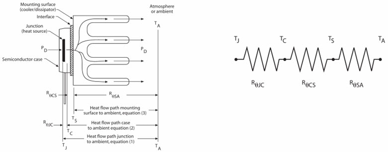
The additions of heat sink and TIM can be seen in the diagram below.
 A heatsink mounted to a semiconductor case. The heat flow, temperatures and thermal resistances in the diagram (left) can be modeled like a network of resistors in series (right). (Image source: Aavid Thermalloy at publication, now Boyd.)
To calculate Rϑ,T requires treating all of the individual thermal resistances between the case, junction, TIM and heat sink as resistors in series. In other words, Rϑ,JC, Rϑ,CS, and Rϑ,SA are added up to find the total resistance. Thus, the calculation becomes:
Rϑ,JC is easy to find, as it’s in the same data sheet as Rϑ,JA. According to the document, Rϑ,JC is 5 °C/W.
Assume a 507302B00000G heat sink, designed to cool a TO-220 device 2.5 W @ 60°C from Boyd, is selected for the system. According to its data sheet, with natural convection dissipating 2 W, the temperature will increase by 50 °C. Thus Rϑ,SA = 50 °C / 2 W = 25 °C/W.
 The 507302B00000G is an aluminum heat sink designed to cool a TO-220 device 2.5 W @ 60°C. (Image source: Boyd)
For the TIM, consider Thermalcote, a thermal silicone compound from Boyd. Its thermal conductivity (k) is 0.765 W/(m °C ). Assuming a 1 mm thickness (L), Rϑ,CS can be calculated using the surface area of the heat sink (A = 19.05 mm x 19.05 mm).
 Thermalcote, a thermal silicone compound. (Image source: Boyd)
So, by plugging everything into the equation:
TJ is now equal to 117.2 °C, well below the maximum rated temperature for the device. Thus, this heat sink is a good option to keep the component working. But is it the best option?
Simulations might be the way to go
The above calculations are still a good option for many engineering scenarios. However, electronics are getting lighter, smaller, more complex, powerful and competitive. Therefore, engineers need to optimize commercial devices and how they are cooled to reduce costs and improve reliability. Here, back-of-the-napkin calculations will not cut it.
Additionally, these calculations use assumptions that may become outdated as electronics shrink. Examples include the atmospheric temperature being 50 °C and heat dissipating uniformly through the heat sink.
Finally, what happens if forced air flow is added? The model doesn’t consider how that air flows within the confined space or how that may affect performance.
The best way to fully understand the heat transfer within modern consumer electronics, and thus size heat sinks and fans optimally, is to use simulations. With simulation, engineers will no longer look at each component in isolation. They can instead model the heat flow through the whole device. This enables them to better optimize designs, heat sinks and fans. Some popular simulation software for this task includes Simcenter Flotherm, Ansys Icepak, Celsius Studio, Altair SimLab, SimScale and SOLIDWORKS Flow Simulation. For more information on heat sinks that can be added to those simulations, click here.

Have questions or comments? Continue the conversation on TechForum, DigiKey's online community and technical resource.
Visit TechForum


