Selecting a Replacement Oscilloscope Probe is Easy—When You Know How
Earlier in my career, I ran a test department with 22 engineers and technicians, and we had 35 or so oscilloscopes. The most common failure in the oscilloscopes was defective probes. Broken probe pins, intermittent connectors, damaged cables—there is literally no end to the things that can happen to an oscilloscope probe. So, we probably replaced over three dozen probes a year.
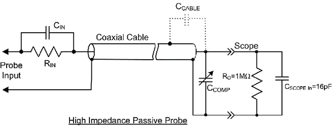
There is very little black magic to finding replacement probes other than a knowledge of how probes work and how they are specified. Almost all oscilloscopes are shipped with one passive probe per channel, making the probe a very common test accessory. Passive probes embody eighty years of technological development, but the basic idea is still very simple. Using Figure 1, the 10:1 passive probe is basically a compensated attenuator that is intended to be connected to the 1 megohm (MΩ) input termination of the oscilloscope. The 1 MΩ input to an oscilloscope can be modeled as a 1 MΩ resistor with a small parallel capacitance.
 Figure 1: The circuit model for a 10:1, high impedance, passive probe which operates in conjunction with the 1 MΩ input of the oscilloscope. (Image source: Art Pini)
The 10:1 attenuation is achieved by putting a 9 MΩ resistor in series with the oscilloscope input, RIN in Figure 1. This combination will attenuate low-frequency signals at the probe input by a factor of ten at the oscilloscope input. For higher frequency signals, the shunt capacitance of the oscilloscope’s input (Cin), added to the coaxial cable’s capacitance, acts as a low-pass filter to the input signals.
Achieving a flat frequency response requires equalization. Adding a series high-pass filter with a break frequency that is the same as the low-pass filter, flattens the frequency response of the probe-oscilloscope combination. This is accomplished by making the time constant RIN x CIN equal to the time constant of Ro x (CSCOPE in+CCABLE+C COMP). Because the input capacitance of the oscilloscope varies slightly, the variable capacitor CCOMP is added to adjust the time constant of the low-pass component. This capacitor is adjusted to set the low-frequency compensation according to the instructions in every oscilloscope manual.
Let’s look at an example of finding a replacement probe. Suppose we try and find a replacement probe for a Teledyne LeCroy HDO4104A 1 gigahertz (GHz), four-channel oscilloscope. This oscilloscope normally ships with four PP018 500 megahertz (MHz) probes. One piece of information we need about the oscilloscope is the input capacitance, CSCOPE in, which can be found on the datasheet. The datasheet lists the input capacitance as 16 picofarads (pF); you can assume a tolerance of ±20% if it is not explicitly listed.
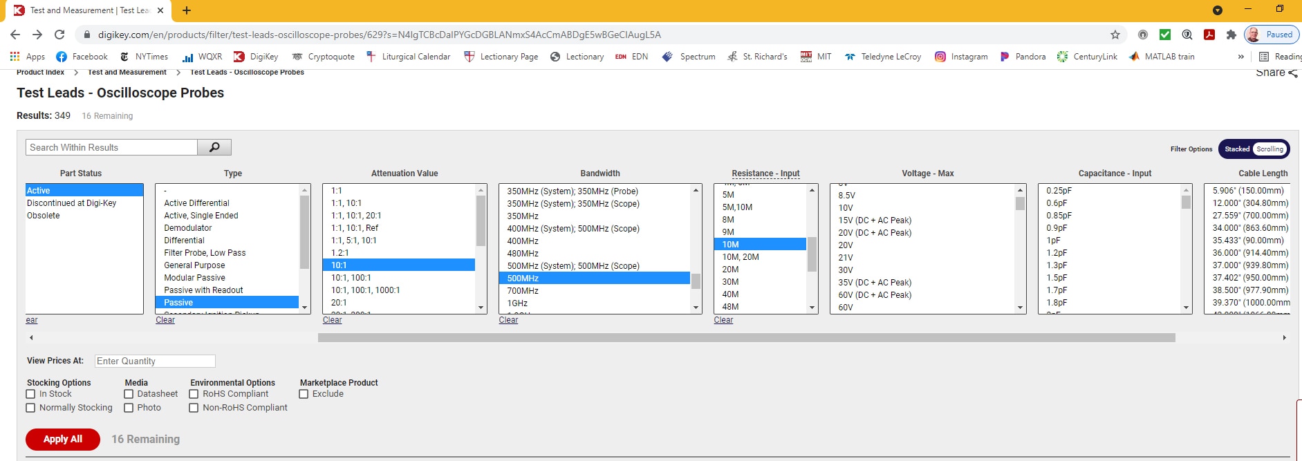
Start by searching on the DigiKey website for oscilloscope probes. One of the search results is Test Leads - Oscilloscope Probes, as shown in Figure 2.
 Figure 2: Use the Test Leads - Oscilloscope Probes page of the DigiKey website to highlight the search criteria: Passive probe, 10:1 attenuation, 500 MHz bandwidth, and a probe input resistance of 10 MΩ. (Image source: Art Pini)
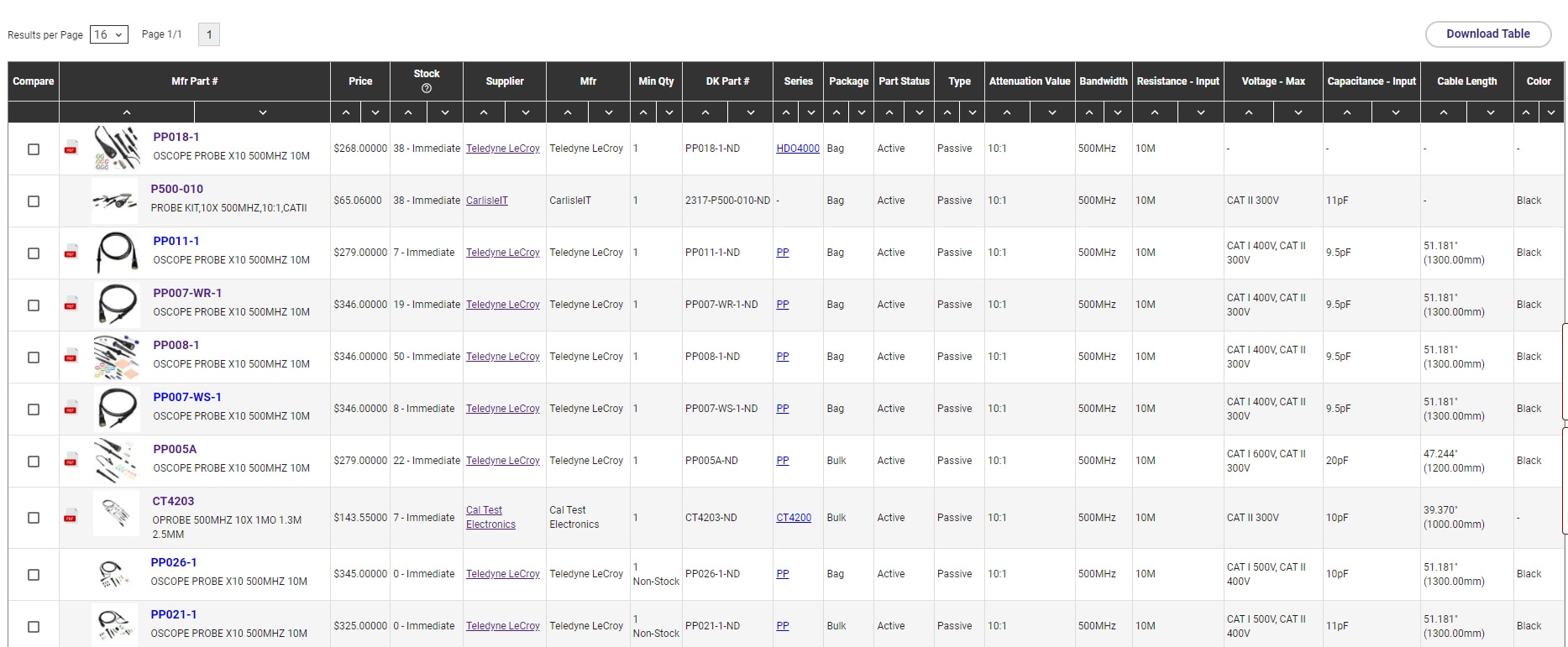
The search produces the 16 product offerings in Figure 3.
 Figure 3: The search results lists 16 probes, the first eight selections of which are in stock. One of the selections is an exact replacement, the PP018, but there are suitable probes from other manufacturers. (Image source: Art Pini)
Of the first eight search results, six are Teledyne LeCroy probes, including the PP018 probe which is supplied with the oscilloscope. There are probes from two other manufacturers: the CT4203 from Cal Test Electronics and the P500-010 from Carlisle Interconnect Technologies. It’s always good practice to evaluate other options.
Consulting the datasheets for each probe, we can compare the key specifications shown in Table 1.
 Table 1: Comparing probe offerings from three different manufacturers using eight key probe specifications. (Table source: Art Pini)
The three probes are pretty closely matched. One key specification that wasn’t mentioned previously is the compensation range. This is the range of scope input capacitance that the probe can match. Since the oscilloscope has an input capacitance of 16 pF ±20%, all of these probes can match it.
The second issue is the diameter of the probe tip. The smaller 2.5 millimeter (mm) diameter permits closer probe spacing without physical interference. The larger 5 mm probe tip is more robust and will be less subject to breakage. This is an engineering decision that can only be made by the user.
Conclusion
While engineers know the importance of taking care of oscilloscope probes as not all damage is immediately visible, there are times when even the most coddled probes fail. As luck would have it, it’s often right in the middle of the most important test.
As shown, using DigiKey’s product search engine and the basic selection guidelines provided, getting a replacement is a relatively straightforward exercise. With the exception of the probe tip diameter, the three probes selected here differ primarily in cost—the ultimate engineering decision.
Alternatively, you can “borrow” from a neighboring desk.

Have questions or comments? Continue the conversation on TechForum, DigiKey's online community and technical resource.
Visit TechForum


