Remote I/O Devices Optimize Automation Control Systems
Factory and industrial automation systems must reliably connect human operators, machinery, computers, and sensors over communications links. This process typically starts with raw materials that are moved through a series of workstations where a product is formed, measured, calibrated, inspected, packed, and shipped, all under the control of a factory automation system.
These systems start with supervisory control and data acquisition (SCADA) architectures, where computers and networked communications systems provide high-level supervision and control of the production processes. The SCADA systems are often located remotely from the actual production facilities, and remote operation is usually accomplished using cloud data services (CDSs), which provide data links and group interoperability.
SCADA systems manage and monitor factory performance by controlling machines through local programmable logic controllers (PLCs) and receiving feedback through networked sensors that guide their work. The PLCs interface with the process plant or machinery. Remote input/output (I/O) components are the communications backbone of the automated factory, as shown in Figure 1.
 Figure 1 : Remote I/O components form the nerve system of a modern automated factory. (Image source: Banner Engineering)
Discrete sensors and actuators monitor and control local operations. Their signals are linked using appropriate hubs and are sent to the master for local processing before being sent to the SCADA system.
Industrial data buses
Automated machines can use many sensors or actuators, but their direct connection to the control room would result in large and expensive cables. To avoid this situation, designers have developed several sensor buses to consolidate these connections. Modbus and IO-Link are two widely used networks (Figure 2).
 Figure 2: IO-Link and Modbus networks reduce the number of wires used in an automated machine, and allow using standardized cable assemblies. (Image source: Banner Engineering)
The networks reduce the number of wires routed to the control room through hubs and controllers. They also permit using standardized cable assemblies, which reduce wiring and maintenance costs.
Banner Engineering designs remote I/O blocks that help automated machine designers enhance their control system architecture. They offer products that decrease wiring complexity by combining multiple signals into an integrated data stream, resulting in lower installation, integration, and diagnostic costs.
Examples of remote I/O blocks
Banner Engineering’s DXMR90-X1 programmable controller (Figure 3) has seven I/O ports and combines data from multiple sources, providing local processing before sending the data to the SCADA system. This controller can collect data from various sensors and convert it to standard Ethernet protocols. The seven ports include four individual Modbus masters, supporting up to four independent networks. It can deploy Modbus slave device data to EtherNet/IP, Modbus TCP, or PROFINET networks. The controller is powered by a 12 to 30 volt DC source with a power consumption of 120 milliamperes (mA) at 12 volts and utilizes LED indicators to report its status.
 Figure 3: The DXMR90-X1 controller has seven I/O ports. (Image source: Banner Engineering)
Housed in a compact enclosure, the controller is ingress protection (IP) rated at IP67, meaning it is dust-tight and protected against short-term immersion in water. It is rated to operate over a temperature range of -40 to +70°C.
The DXMR90-X1 uses standard M12 connectors, with a single male M12 port (Port 0) for power and Modbus RS-485 connections, and a single female M12 port for daisy-chaining the Port 0 connections. There are also four female M12 ports for the Modbus master connections and a female M12 D-Code Ethernet connector.
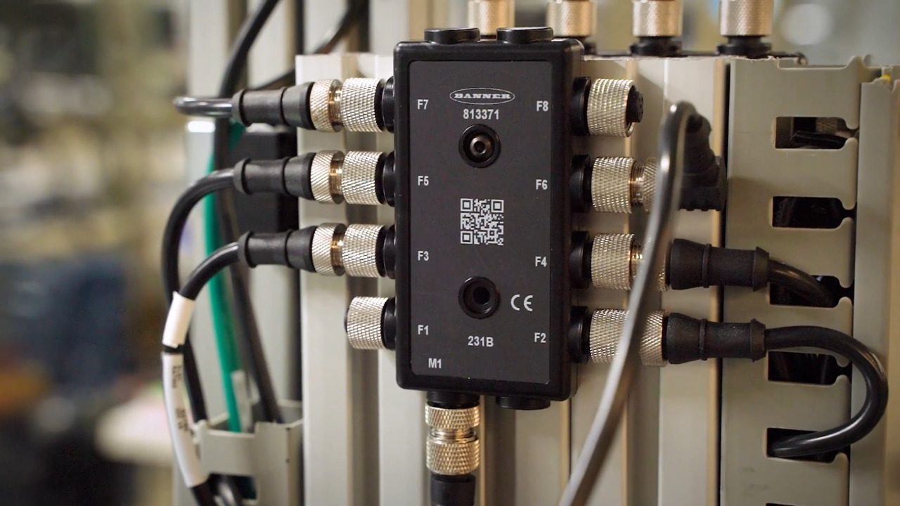
The controller is coupled to remote sensors via a hub. The Banner Engineering R95C-8B21-KQ is an eight-port IO-Link hub (Figure 4) that offers an easy way to connect non-IO-Link devices to an IO-Link system. It connects two discrete channels to the eight four-pin M12 connector ports, which can be configured as 16 inputs or as 8 inputs and 8 outputs. Data from the channels is connected to an IO-Link master.
 Figure 4: The R95C-8B21-KQ eight-port hub supports both NPN and PNP outputs. Indicator LEDs report port activity and IO-Link status. (Image source: Banner Engineering)
Two configurable I/O pins per port support PNP (sourcing) or NPN (sinking) outputs. LEDs that indicate port activity are placed on each side for mounting flexibility. The hub also supports host mirroring, where a selected port input or output discrete signal can be routed to the PLC or the host connection.
The hub is rated to operate off 18 to 30 volts DC with a maximum current draw of 400 mA. It can supply a pass-through current of up to 500 mA per port and is protected against reverse polarity and power transients.
Packaged in a rugged nickel-plated brass and PVC body, the hub has IP65, IP67, and IP68 ratings for indoor use only.
Analog signals predate automation, but since many sensors still have them as outputs, they need to be converted to Modbus or IO-Link protocols. The Banner Engineering R45C-2K-MQ 2-port converter reads two analog signals as a voltage or a current and outputs them in a Modbus protocol. Analog inputs are made via two M12 female connectors, while the output is via a five-pin M12 male connector. LEDs indicate the input and output status. The R45C-2K-MQ is powered from an 18 to 30 volt DC source with a maximum current draw of 4 amperes (A) at 24 volts. The converter operates over a temperature range of -40 to +70°C and is environmentally rated at IP65, IP67, and IP68 for indoor use only.
Data converters can also take digital commands from the master controller and output an analog voltage for devices such as pneumatic actuators, solenoids, or motor starters. The converter can be located near the controlled device, minimizing analog signal losses and electromagnetic interference. The Banner Engineering R45C-K-UQ converter (Figure 5) allows automation designers to output an analog value of voltage or current by sending the numerical analog value from the IO-Link master. The converter has an output voltage range of 0 to 11 volts and an output current range of 0 to 24 mA.
 Figure 5 : An IO-Link-to-analog output converter produces a current or voltage output controlled by the IO-Link master. (Image source: Banner Engineering)
Like the other Banner Engineering remote I/O devices, it has environmental ratings of IP65, IP67, and IP68, with an operating temperature range of -40 to +70°C. It can be powered from an 18 to 30 volt DC source, drawing only 50 mA, and can pass power up to a maximum current of 4 A. Connectivity to the IO-Link master is via a conventional four-pin M12 male connector. The analog output uses a four-pin female M12 connector.
Conclusion
Banner Engineering Remote I/O Blocks help automation designers optimize the deployment of control systems. Multi-protocol support reduces wire count and installation costs, while onboard programmability provides design flexibility and eases system integration.
About this author

Arthur (Art) Pini is a contributing author at DigiKey. He has a Bachelor of Electrical Engineering degree from City College of New York and a Master of Electrical Engineering degree from the City University of New York. He has over 50 years experience in electronics and has worked in key engineering and marketing roles at Teledyne LeCroy, Summation, Wavetek, and Nicolet Scientific. He has interests in measurement technology and extensive experience with oscilloscopes, spectrum analyzers, arbitrary waveform generators, digitizers, and power meters.

Have questions or comments? Continue the conversation on TechForum, DigiKey's online community and technical resource.
Visit TechForumMore Blogs from this Author