I/O Voltage Standards and Their Role in Ensuring Microcontrollers Speak the Same Language
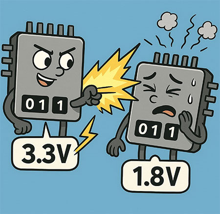
Imagine trying to communicate with a foreigner in your native language (Figure 1), only to realize that not only do they not understand you, but your “yes” actually means “no” in their language. This is exactly what happens when two integrated circuits (ICs) with incompatible I/O standards attempt to communicate. The result is confusion at best and hardware damage at worst.
 Figure 1: AI-generated image symbolizing the confusion of using different IO standards. (Source: AI-generated)
Microcontrollers work in binary logic of 0's and 1's. There are voltage ranges that correspond to these logic levels. For instance, one microcontroller may read a logic '0' as anything lower than 0.3 V, and a '1' as anything that's higher than 2.7 V, and as high as 3.3 V. But the other microcontroller can read a '1' as anything that starts at 1.2 V and is as high as 1.8 V. If the first microcontroller sends a 3.3 V signal to the second (Figure 2), it could exceed the voltage tolerance of the receiving device, potentially causing permanent damage.
 Figure 2: Depiction of two ICs of incompatible IO standards communicating. (Source: AI-generated)
This is why understanding and managing I/O voltage compatibility is critical in embedded system design. Without proper level shifting or voltage translation, even a simple connection between two chips can lead to unpredictable behavior or hardware failure.
The Role of I/O Voltage Standards
I/O voltage standards define the acceptable voltage levels for digital logic signals. It specifies what constitutes a logical high (1) or low (0). These standards ensure that devices can correctly interpret signals and respond appropriately. Without a commonly agreed standard about these levels, devices may misread signals or fail to communicate with each other.
Terminologies defined by the standards:
- VIH (Input High Voltage): Minimum voltage recognized as a logic high.
- VIL (Input Low Voltage): Maximum voltage recognized as a logic low.
- VOH (Output High Voltage): Minimum voltage output as a logic high.
- VOL (Output Low Voltage): Maximum voltage output as a logic low.
For successful communication, the output levels of one device must fall within the acceptable input range of the receiving device.
Single Ended IO Standards
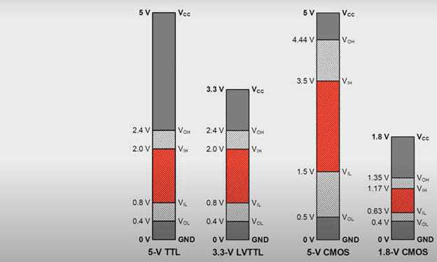
Single-ended Input-Output (SIO) standards (Figure 3) are one of the most popular Input-Output (I/O) standards. They use a single wire referenced to a common ground for signal transfer. When it comes to lower-speed and low-complexity designs, SIOs are a cost-effective and simpler alternative compared to differential signaling standards, which use two complementary signals.
The Low Voltage Complementary Metal-Oxide Semiconductor (LVCMOS) is a common single-ended standard, often referred to as LVMOS in some contexts. LVCMOS typically operates in 1.8 V, 2.4 V or 3.3 V and defines specific thresholds for logic highs and lows. The simplicity related to the SIO standards comes at a cost, SIOs such as LVCMOS are susceptible to noise and signal degradation over long distances or at high frequencies. Ensuring proper voltage compatibility, using level shifters, is critical when interfacing LVCMOS with devices operating at different voltage domains.
 Figure 3: Voltage levels of different IO standards. (Source: Texas Instruments)
Challenges in I/O Interfacing
1. Voltage Mismatch
The most common issue related to interfacing devices operating at different voltage levels is voltage mismatch. For example, connecting a 3.3 V output to a 1.8 V input without level shifting can damage the lower-voltage device (Figure 2).
To mitigate this, one must ensure that the input high voltage (VIH) and input low voltage (VIL) levels of one IC match the output high voltage (VOH) and output low voltage (VOL) levels of the other.
2. Signal Integrity
At high speeds, reflections, ringing, and crosstalk can corrupt signals. Proper termination, impedance matching, and trace routing are essential to maintain clean signal transitions.
3. Power Supply Domains
In systems with multiple voltage rails, care must be taken to isolate or translate signals between domains. Level shifters, voltage dividers, or open-drain configurations with pull-up resistors are common solutions.
Advanced Logic Families: LVPECL, CML, VML, and LVDS
In high-speed communication systems, logic families like LVPECL (Low Voltage Positive Emitter Coupled Logic), CML (Current Mode Logic), and VML (Voltage Mode Logic) are used (Table 1). These offer faster transitions and better noise immunity but require careful design:
- LVPECL: Operates around 3 V, with differential signaling and high-speed performance
- CML: Uses constant current sources for fast switching and low jitter
- VML: Less common, but offers voltage-mode signaling with load-independent swing
- LVDS: Widely used for moderate-speed, low-power differential signaling
 Table 1: Voltage parameters by logic level LVPECL, CML, VML and LVDS. (Source: Texas Instruments)
Best Practices for I/O Interfacing
- Always check datasheets for VIH, VIL, VOH, and VOL values.
- Use level shifters when interfacing across voltage domains.
- Test early and often with oscilloscopes and logic analyzers.
I/O interfacing is more than just connecting pins, it's about ensuring that every signal is understood exactly as intended. As embedded systems become more complex and operate across multiple voltage domains and logic families, mastering I/O compatibility becomes critical.
By understanding voltage standards, anticipating mismatches, and applying best practices, we can design robust, reliable systems that communicate clearly without any translation errors. However, if it is required to interface ICs of different I/O standards, one way of mitigating signal level mismatch is by using level shifters.
Level Shifter
A level shifter(LS), (also known as a voltage translator), is a circuit used in embedded systems to safely interface between components operating at different voltage levels. Suppose a microcontroller operating at 3.3 V needs to communicate with a sensor that is running on 1.8 V logic, the level shifter ensures that signals are correctly translated between the two, without any risk of damage or logic errors. Depending on the protocol used, level shifters can be categorized as unidirectional or bidirectional. LSs are commonly implemented using MOSFETs, buffer ICs or dedicated translator chips. They play an integral role in the maintenance of signal integrity and in protecting components in mixed-voltage environments.
 Figure 4: Eight channel level shifter module. (Source: SparkFun)
Additional Resources

Have questions or comments? Continue the conversation on TechForum, DigiKey's online community and technical resource.
Visit TechForum


