How to Properly Measure Resistance
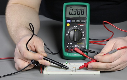
The last video demonstrated the basics of how to use manual and auto-ranging multimeters. The video below will demonstrate how to test voltage, current, and resistance in a circuit. For the purpose of covering one topic at a time, I will cover some information on measuring resistance in this blog, with separate blogs covering voltage and current to follow.
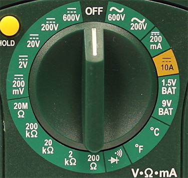
First, plug the black probe into the “COM” port and the red probe into the port labeled Ω. Note: this port may also have other symbols for various measurements as well. Next, if using an auto-ranging multimeter simply turn the dial to Ω. If using a manual-ranging meter then you’ll want to have some sort of idea what range you’re dealing with. If you are unsure, start with the highest range and reduce as needed for a more refined result. See an example of a manual-ranging meter below.
 *Note: Each meter will look different and have their own max values, this image is just an example and not a direct representation of every meter.
Resistance measurements can be affected by other components within a circuit. The only reliable way to measure resistance is to remove the component from the circuit completely and test it. If this isn’t something you’re able to do, you may have to resort to Ohm’s Law (R=V/I) to find the value.

When trying to find a resistor value, you can read the color code on the resistor and use this calculator to help decipher the value. If you’re taking the measurement with a multimeter to verify the value, just remember that resistors all have a tolerance level so it may not be spot on with what the color code says it should be.

Have questions or comments? Continue the conversation on TechForum, DigiKey's online community and technical resource.
Visit TechForum


