How to Implement the 10Base-T1S Interface Toward a Unified Network Architecture for Automobiles
It’s hard enough to design the modern automobile without having to deal with multiple communications networks and the redundancies and data conversions therein. It turns out that there may be a better way. 10Base-T1S is an automotive Ethernet network standard developed as part of the IEEE 802.3cg 2019 standard published in 2020. It is a 10 megabit per second (Mbit/s) interface that fills a gap in Ethernet coverage in automotive applications in the area of low-speed data communications. In doing so, it allows the same software stack and communications mechanisms to be used throughout an automobile, greatly simplifying design, implementation, and system maintenance. Let’s look at how it works and how you can get started.
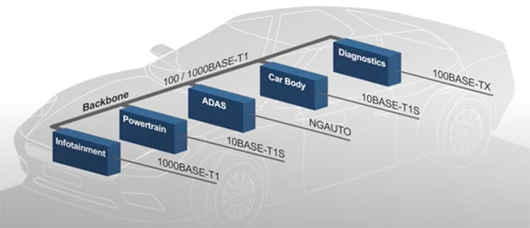
10Base-T1S runs over a single, unshielded twisted pair and provides what the industry classifies as “Ethernet to the Edge” technology. It complements existing higher-speed Ethernet automotive buses, including 100Base-T1 and 1000Base-T1, known as single pair Ethernet (SPE) (Figure 1).
 Figure 1: 10Base-T1S fills the low data rate segment of the fully integrated Ethernet automotive network. (Image source Microchip Technology)
The link operates as a half-duplex bus with a maximum length of 25 meters (m). It supports multidrop connections from two to eight nodes. The “S” in the standard name indicates a short-range implementation. 10Base-T1S is intended to supplant existing buses like CAN, CAN FD, LIN, and RS-485 that tend to form “communications islands”.
A related standard, 10Base-T1L, is a long-range implementation intended for industrial applications.
How 10Base-T1S works
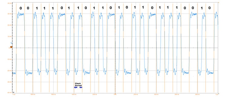
10Base-T1S uses differential Manchester encoding (DME). DME encodes data using the presence or absence of a transition within a clock cycle to indicate the logical state of the signal. If there is no transition during a clock cycle, the data state is a logical 0. If there is a transition (either positive or negative) in the middle of the clock cycle, then the data state is a logical 1 (Figure 2).
 Figure 2: An example of a 10Base-T1S differential Manchester encoded data stream. Vertical orange lines mark the clock intervals. A transition during the clock interval represents a 1; no transition during the clock interval represents a 0. (Image source: Art Pini)
Logical 1 data may go high or low during the clock interval only; relative to the previous state, so no reset transitions are needed. One data bit occurs in every clock interval, making clock recovery easier in a noisy automotive environment.
In a multidrop environment, there are multiple devices connected to the bus. 10Base-T1S uses physical layer (PHY) collision avoidance (PLCA) to minimize dead time and avoid data collisions when multiple devices attempt to talk simultaneously. PLCA establishes a transmit cycle that is used to orchestrate transmit opportunities on the bus. With PCLA, each node’s PHY is assigned a unique PHY ID. Only the PHY holding that transmit opportunity is permitted to transmit.
The transmit opportunities are allocated in a round-robin algorithm starting from PHY ID = 0, which is allocated to the master. A new cycle is started when the master node sends a synchronization pattern called the BEACON to signal the start of the PLCA cycle. Nodes can start a transmission only when the transmit opportunity matches their own node ID (Figure 3).
 Figure 3: An example of the PLCA cycle starting with the beacon synchronization pattern (B). The leftmost cycle is the minimum bus cycle time. The next cycle has a number of permissible transmission variants. (Image source: Art Pini)
Any node can skip a transmission opportunity by leaving the time slot unused, as indicated by the “N”. During the assigned slot, the node may transmit its data. Nodes may enlarge their time slot, as shown by slot 2 (blue). The transmitting node can insert a “commit” in its time slot to extend the time slot to compensate for media access control (MAC) delays, as exhibited by time slot 3 (yellow). A node may “burst mode” a message with high priority, as shown by the 0 PHY ID (green).
PLCA is well structured to prevent data packet collisions and maximize the data rate.
The main advantage of 10Base-T1S is that it simplifies automotive networking by building on the existing support base of Ethernet. It uses the same software stack as 100Base-T1 and 1000Base-T1 without gateways, just different PHY configurations, and cabling.
Getting started with 10Base-T1S
Microchip Technology is already providing three 10Base-T1S transceivers: the LAN8670B1-E/LMX, the LAB8671B1-U38, and the LAN8672B1-E/LNX. These transceivers include all of the 10Base-T1S features, differing only in their physical package and electronic control unit (ECU) interface. The LAN8670 uses a 32-VQFN package and supports both media independent interface (MII) and reduced media independent interface (RMII) ECU interfaces; the LAN8671 is contained in a 24-VQFN package and supports the RMII interface; the LAN8672 is in a 36-VQFN package and supports the MII interface. All three transceivers operate over the automotive extended temperature range of -40°C to +125°C and off a 3.3 volt supply.
Need to see what these transceivers can do? Microchip offers two evaluation boards based on the LAN8670. The first is the EV08L38A Ethernet PHY Interface Evaluation Board which includes a USB interface, allowing a computer to connect via USB2.0 to the 10Base-T1S Ethernet network. The second is the EV06P90A, which uses the RMII interface for connection to one of Microchip’s ECUs.
Conclusion
While the many communications networks found in automobiles each have their place, from an overall implementation complexity and cost perspective, limiting the variety of networks is generally good practice. With Ethernet already in automobiles, it’s logical to extend its use as much as possible. 10Base-T1S is an automotive Ethernet interface that enables this extension. In doing so, it reduces costs by eliminating legacy gateways for a total Ethernet network and connecting multiple PHYs into a common bus to reduce cabling and switch ports.

Have questions or comments? Continue the conversation on TechForum, DigiKey's online community and technical resource.
Visit TechForum


