Guidelines in Paralleling DC-DC Converters
Introduction
In designing a power system, various sub-functions are typically specified in terms of the output power, noise characteristics, and stability required by the load during start-up and steady-state conditions. Ensuring power stability is critical, with clear provisions and requirements in place to manage power transients, input power variability, and the system’s ability to adapt or respond accordingly. Additional factors such as size, weight, cost, and reliability are also key considerations.
When developing a conceptual design that meets these specifications, engineers often look to existing products within the company or the industry for re-use, aiming to implement the necessary functions efficiently. The push for product re-use is largely driven by management's goals to reduce cost, shorten development schedules, and minimize risk. In this process, designers may encounter situations where existing DC-DC converters do not meet the required power output, leading to the question: can multiple DC-DC converters be paralleled to achieve the desired power levels?
This blog addresses the considerations and limitations involved in paralleling DC-DC converters.
Considerations
It can be tempting to connect two or more DC-DC converters in parallel to achieve double or triple the derated power. However, as we will discuss, this approach is not straightforward and comes with several challenges. There are potential issues like system instability, higher ripple, and inefficient use of space on the Printed Wiring Board (PWB), which can outweigh the benefits of paralleling multiple converters.
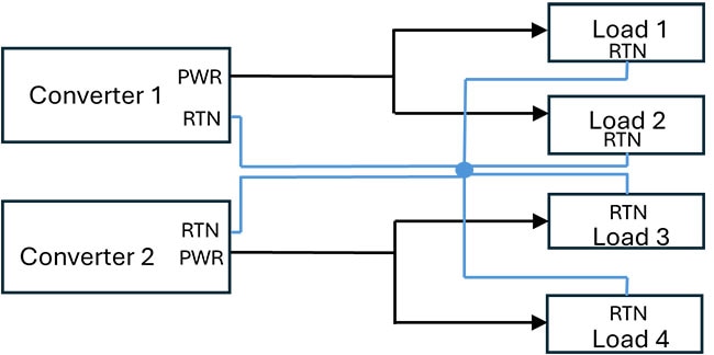
The simplest solution is to assess whether the load can be partitioned. If the load consists of multiple devices, there may be no need to parallel converter outputs. Instead, you can assign each converter to power a specific subset of the load, as illustrated in Figure 1.
 Figure 1: Powering Multiple Loads from Multiple Converters. (Image source: Ganmar Technologies
Ensure that your load returns follow a common “Kelvin” single-point star configuration. This minimizes the risk of ground loops, but it's crucial to consult your system grounding design team for specific recommendations.
If your loads cannot be partitioned, more complex paralleling strategies must be employed. In most converters, the feedback signal is directly sampled from the output connected to the load. This feedback node can significantly impact loop performance and may lead to instability. To avoid this, it's essential to understand the internal feedback loop's operation and how to integrate it correctly. Additional circuitry will be required to control and ensure equal power sharing between the parallel converters. While designing this can be intricate, many manufacturers provide documentation and guidance for implementing such schemes. However, design and testing can still be challenging, requiring a knowledgeable and experienced designer. Since these designs depend on the specific converters used, this blog will not delve into further detail.
Paralleling Current Source Converters
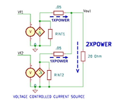
Figure 2 shows a simplified model for paralleling two converters. When converters function as current sources, paralleling them results in the sum of the individual currents.
 Figure 2: Illustrative Model of Paralleling Current Source Converters. (Image source: Ganmar Technologies)
Paralleling using GMR10DX Converters
Ganmar Technologies' GMR10Dx series of power converters feature a topology that allows their outputs to behave like current sources. In Figure 3, the feedback loop is connected to the transformer’s primary side, isolating it from the output load circuitry.
 Figure 3: GMR10Dx Topology. (Image source: Ganmar Technologies)Figure 3: GMR10Dx Topology. (Image source: Ganmar Technologies)
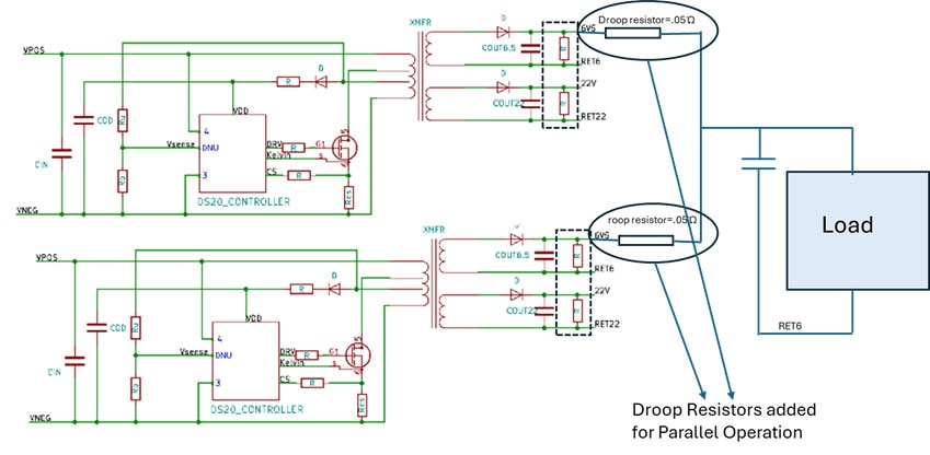
As shown in Figure 4, paralleling these converters requires minimal additional circuitry, primarily the inclusion of droop resistors. Droop resistors help accommodate the variability in the output voltage of each converter. It is also good practice to provide a minimum load for the other outputs to ensure well-regulated performance when using the GMR10DX family. Additionally, place 22 uF/25 V MLCC capacitors (X7R or X5R) and 470 uF/35 V tantalum capacitors at the point of load to support local pulse currents, a standard practice when powering ICs. Be mindful of thermal management, as heavy loads may exceed component ratings. For assistance, Ganmar Technologies' Technical Support is available to help with design challenges.
 Figure 4: Paralleling Converters to Power Larger Loads. (Image source: Ganmar Technologies)
Other Recommendations
Grounding management is a critical, yet sometimes overlooked, aspect of system engineering. When powering converters from a rectified AC source (single-phase or three-phase), it is recommended to keep the primary side return separate.
Conclusion
It is feasible to deliver higher startup or bias power to your loads using multiple DC-DC converters. If your load consists of several devices, each can be powered by individual converters, all connected to a single common return. For non-partitionable loads, converters must be paralleled with careful attention to feedback loop stability. The GMR10Dx family can be paralleled with minimal additional components, and Ganmar Technologies provides technical support to help with application details.

Have questions or comments? Continue the conversation on TechForum, DigiKey's online community and technical resource.
Visit TechForum


