Getting Started with Machine Vision using TinyML and OpenMV – Part 1
There are many application problems that machine learning and tinyML can potentially solve for embedded systems engineers. One unique problem that is very difficult to code from scratch is object detection and recognition within an image. As it happens, detecting and recognizing objects is a perfect application for tinyML. However, getting started with tinyML and machine vision (MV) can be complicated. In the next several posts, we will explore how to get started with MV using the OpenMV camera.
Introduction to the OpenMV Cam H7
Suppose you are interested in MV for low-power applications using a microcontroller. In that case, you either have to custom design your camera module or find one already commercially available. Creating a module from scratch would be fun, costly, and time-consuming. One interesting commercially available solution is the OpenMV Cam.
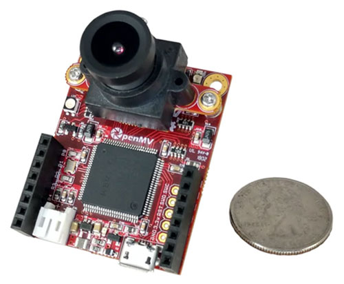
The OpenMV Cam is a small, Arduino-like development board that includes everything a developer needs to get started with MV. First, it's essential to realize that there are different hardware versions. The latest version is the OpenMV Cam H7 (Figure 1). The Cam H7 is based on an STMicroelectronics’ STM32H743VI microcontroller; this uses an Arm Cortex-M7 architecture with a clock speed of 480 megahertz (MHz). The part also has 1 megabyte (Mbyte) of SRAM and 2 Mbytes of flash. When working with MV and learning applications, it's always good to have plenty of memory available. The Cam H7 uses an MT9M114 camera module that can capture images of 640 x 320 in 8-bit grayscale at 40 frames per second (fps) or 320 x 240 QVGA at 40 – 80 fps. The camera module can be changed based on the application's needs.
 Figure 1: The OpenMV Cam H7 module has everything needed to get started with MV designs. (Image source: OpenMV)
The OpenMV development environment
The OpenMV integrated development environment (IDE), shown in Figure 2, is how developers interact with the Cam H7. The IDE provides developers with the ability to edit Python scripts that will run on the module. The Cam H7 uses MicroPython, a port of C Python specifically designed to run on microcontroller-based systems. Developers can then connect to their Cam H7, load their script onto the device, and run their application. The IDE can also be used to get a live feed of the Cam H7 frame buffer images.
 Figure 2: The OpenMV development environment includes everything developers need to program and interact with the Cam H7, like a text editor, terminal, and image capture display. (Image source: OpenMV)
Developers looking to start using the module for machine vision and eventually machine learning don't need to look very far. The OpenMV IDE includes example scripts that range from putting the system into a low-power mode to object and face detection. There are also examples of interfacing the module with external development boards like Wi-Fi, inertial measurement units (IMUs), and other options.
Detecting a circle in an image
The OpenMV IDE includes a HelloWorld script that allows a developer to connect to the camera and take pictures that feed the frame buffer. For this post, I thought it would be interesting to look at an example that can detect something in an image, such as a circle.
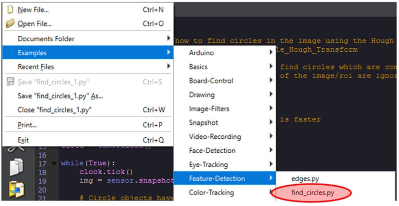
If you were to open OpenMV IDE and click on File->Examples->Feature-Detection->find_circles.py (see Figure 3), it would bring up a script that does just that. It's super easy to test this script; first, you need to get a piece of paper or a sticky note and draw a circle (Please don't judge my drawing ability, it's pretty horrendous!). Next, on the lower left-hand side of the IDE, you'll notice a connection button. Click that to connect to the Cam H7. Next, click the green play button immediately under the connect button. Finally, point the Cam H7 at the circle you drew and monitor the frame buffer in the OpenMV IDE.
 Figure 3: Navigating to the find_circles.py example script in the OpenMV IDE. (Image source: Beningo Embedded Group)
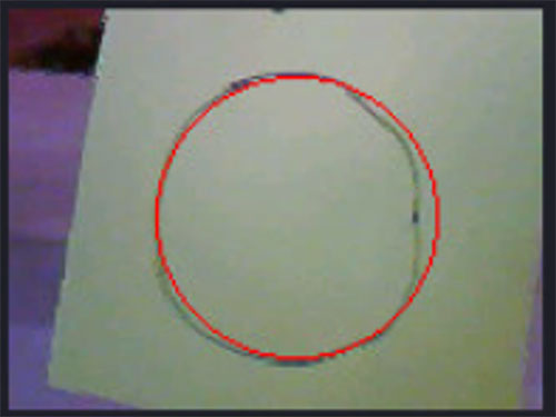
You should notice that periodically, a red circle will be drawn in the frame buffer that overlaps the circle you drew, as shown in Figure 4. Notice that even though my artistic ability is left wanting, the Cam H7 was still able to detect that there was a circle-like thing in the image that was captured. A circle is our first detection in this blog series but not our last! Let's take a look at the example script to understand what it is doing.
 Figure 4: The find_circles.py example script will add a red circle to the frame buffer, highlighting when a circle is detected. (Image source: Beningo Embedded Group)
Analyzing the find_circles.py example
The script that OpenMV IDE provides to detect circles is straightforward. First, the script imports the Python libraries needed and initializes the camera sensor and clock, as shown in Listing 1.
Copyimport sensor, image, time

sensor.reset()
sensor.set_pixformat(sensor.RGB565) # grayscale is faster
sensor.set_framesize(sensor.QQVGA)
sensor.skip_frames(time = 2000)
clock = time.clock()
Listing 1: Example code that initializes the camera sensor. (Code source: OpenMV)
Next, an infinite loop continuously runs the application, just like in any standard embedded application. Then, finally, there is the magic that causes the detection. Take a moment to examine Listing 2.
Copywhile(True):
  clock.tick()
  img = sensor.snapshot().lens_corr(1.8)

  for c in img.find_circles(threshold = 2000, x_margin = 10, y_margin = 10, r_margin = 10,
      r_min = 2, r_max = 100, r_step = 2):
    img.draw_circle(c.x(), c.y(), c.r(), color = (255, 0, 0))
    print(c)

  print("FPS %f" % clock.fps())
Listing 2: Example code that reads the camera sensor and searches for circles in the image. (Code source: OpenMV)
The code in Listing 2 starts by taking a snapshot image. A method named find_circles—included in the OpenMV libraries—is then used to search the image for circles. You can read the comments in the actual source code example for details on the parameters, but we are most interested in the r_min, r_max, and r_step parameters. The r_min parameters specify the minimum circle radius that can be detected. The r_max parameter sets the maximum. The program will see circles between 2 and 100 pixels in the example.
When a circle is detected, the draw_circle method, along with the circle x, y, and radius values, is used to draw a circle over the detected circle. You'll notice that color is specified in R, G, and B notation, in this case, drawing a red circle.
Conclusion
Machine Vision and TinyML can be leveraged by developers and applied to nearly an infinite number of use cases. In this post, we just introduced the OpenMV Cam H7 and OpenMV IDE to get you up and running to detect circles. Detecting circles, though, didn't require tinyML, just a few library functions. In the next post, we will explore the built-in machine learning examples before moving on to a more complex example where we will train and deploy our detection project.

Have questions or comments? Continue the conversation on TechForum, DigiKey's online community and technical resource.
Visit TechForum


