Discrete or Integrated: Exploring Options for Gigabit Ethernet Front-End Protection
Gigabit Ethernet (GbE) is a relatively robust, high-speed communication system widely used across domestic, commercial, and industrial premises. However, that robustness will be challenged if an unexpected, high-level, transient voltage zaps the connector. Such transients can be caused by lightning strikes and electrostatic discharge (ESD) events. Without protection, the voltage spike conducts through the connector and can quickly fry the silicon of the GbE physical layer (PHY).
It is no surprise, then, that the design of the GbE front-end demands a high degree of protection. This is typically achieved using an isolation transformer. The GbE specification (IEEE 802.3) defines a minimum isolation rating of 2.1 kilovolts (kV) for the GbE front-end, but most commercial transformers offer isolation ratings of 4 to 8 kV. Additional protection for GbE interfaces comes in the form of a common mode choke (CMC), an inductor used to block higher-frequency alternating current (AC) and help reduce the severity of ESD spikes.
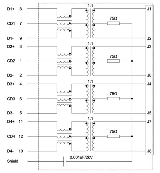
A “Bob Smith” termination can add a further degree of protection. The design is named for a now-expired patent filed by Robert W. Smith in 1993. The patent covers “an apparatus for terminating the cable to minimize emissions radiating from the cable and susceptibility of the cable to outside interferences.” In GbE applications, the Bob Smith termination generally uses a 75 ohm (Ω) resistor to implement a common-mode impedance match to help reduce common-mode emissions for signal pairs collectively connected via a capacitor to ground (Figure 1).
 Figure 1 : Front-end voltage spike and ESD protection for each channel in a Gigabit Ethernet system typically comprises an isolation transformer, a CMC, and a Bob Smith termination. (Image source: Würth Elektronik)
Comparing discrete with integrated GbE protection
As a designer, you have three standard options for implementing your GbE protection. Option one is to select your own transformer, CMC, Bob Smith termination, and other earthing components, and settle in to design the circuitry for your PC board. The advantages are that you can maximize the level of protection by choosing high-end components, save some cost on those components compared with other options, and enjoy the satisfaction of crafting an original design. The downside is that the design process is tricky and will likely take time and individual components will take up more space than integrated solutions.
Option two is to choose a module that integrates the transformer and the CMC into a single component. The module might integrate several transformers and CMCs into one component to accommodate multiple channels. The advantages here are space savings and an easier design cycle, though you might still need to include the Bob Smith termination and other earthing components.
Würth Elektronik offers a range of such modules in its WE-LAN line. Consider the 749020310 WE-LAN AQ 10/100/1000 Base-T surface mount device (SMD). This component protects four channels and has an inductance of 350 microhenries (µH), a differential common-mode rejection ratio (CMRR) across a 60 to 100 megahertz (MHz) frequency range of -30 decibels (dB), and an insulation test voltage pass of 1500 volts (RMS) for one minute.
Option three is to select an RJ45 connector with an integrated transformer and CMC. This is the most compact design. The trade-off is a lack of GbE front-end component flexibility. An example of such an RJ45 connector is Würth Elektronik’s 7499611420 WE-RJ45LAN transformer 10/100/1000/10G Base-T, which integrates four protected channels, including transformers, CMCs, and even 75 Ω termination resistors. The connector features an inductance of 120 µH, a differential CMRR across a 1 to 100 MHz frequency range of -28 dB, and an insulation test voltage pass of 1500 volts (RMS) for one minute (Figure 2).
 Figure 2 : Würth Elektronik’s 7499611420 integrates four channels of isolation transformer, CMC, and termination resistor protection. (Image source: Würth Elektronik)
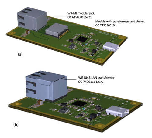
The space savings from using the RJ45 connector with integrated protection are impressive, making the component useful for space-constrained applications (Figure 3).
 Figure 3 : Compared to separate components (a), integrating GbE protection into the RJ45 connector (b) eliminates the need for the protection module and saves PC board space. (Image source: Würth Elektronik)
Testing electromagnetic compatibility
You might wonder whether packing the circuitry tightly into the RJ45 connector undermines the protection provided by the circuit. The answer comes in an extensive application note (ANP116), “Gigabit Ethernet interface from an EMC perspective,” in which Würth Elektronik tests the reference designs shown in Figures 3 (a) and (b).
One important point is the impact the Ethernet cables can have on the electromagnetic compatibility (EMC) of the GbE system: it turns out that cable type does not significantly affect the EMC behavior, but unshielded cables (perhaps not surprisingly) exhibit higher interference emissions and reduced immunity levels (up to 20 dB lower) than shielded designs.
So much for the cables; what of the front-end assemblies? In the application note, Würth Elektronik concludes that the two reference designs differ in electromagnetic compatibility (EMC) behavior, mainly concerning their tolerance of high voltage ‘burst’ levels.
These bursts arise when switching inductive circuits causes sparking. The burst interference couples strongly into the Ethernet conductor structure. The discrete (module) Ethernet interface design is recommended when enhanced performance is required in EMC environments with high burst levels.
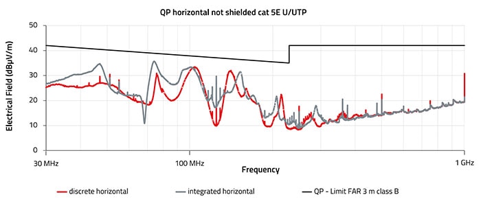
Apart from this difference in EMC when subject to bursts, the EMC behavior of the two types is comparable, and both designs consistently outperform U.S. Federal Communications Commission (FCC) Class B certification limits for residential equipment across a 1 gigahertz (GHz) frequency range by at least 10 dB (Figure 4).
 Figure 4 : Comparison of discrete (module) and integrated (RJ45 connector) EMC performance (radiated inference emission) with the FCC Class B certification limits for residential equipment. (Image source: Würth Elektronik)
Figure 4 is the worst-case scenario, with the unshielded cables in a horizontal antenna polarization. Shielded cables further reduce emissions.
Experiment with transformer options using design kits
Since circuit protection is mandatory for GbE installations, the components have been refined over the years, and the circuit design is mature. As a result, reference designs and discrete components allow an engineer to construct their own implementation, but many commercial options offer integrated solutions.
Würth Elektronik offers a handy design kit, the 749945. The kit is full of WE-RJ45 LAN transformer examples that you can play around with.
Conclusion
Popular options for GbE circuit protection include modules integrating the protection circuitry and situated between the RJ45 connector and the GbE PHY, or RJ45 connectors that dispense with the module by housing the protection circuitry inside their enclosure. The choice comes down to a trade-off between space and front-end design flexibility, with both offering protection well within certification limits.

Have questions or comments? Continue the conversation on TechForum, DigiKey's online community and technical resource.
Visit TechForum


